Contents: Removal ↳ Installation ↳
Removal
Door Lock (Hatchback) - Models before 1996
1. Disconnect the negative battery cable.
2. After opening the door to access the lock, pull out the moisture seal. Remove the screws and fasteners and remove the trim panel from the rear of the luggage compartment.
3. Unhook the luggage net. Then remove the screws and fasteners and remove the trim from the rear cross member.
4. Remove the screws and pull the rear lamp unit cover out of the guides.
5. Release the open door alarm microswitch from the retainer next to the lock.
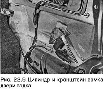
6. Pull the cable sheath out of the lock bracket. Lift the cable until it aligns with the slot in the cylinder lever and disconnect the cable (see Fig. 22.6).
7. Pull out the elastic lock retainer.
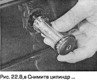
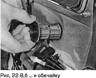
8. Disconnect the cable support bracket from the cylinder and remove the cylinder and the shell (see Fig. 22.8, a, b).
Door Lock (Hatchback) - Models since 1997
9. See. paragraph 19, points 8...12.
Lock cylinder (Universal)
10. Disconnect the negative battery cable.
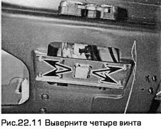
11. Unfasten and remove the tailgate trim panel. Unscrew the four screws and remove the access plate (see Fig. 22.11).
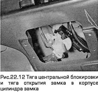
12. Pull the central locking rod and the lock opening rod out of the lock cylinder housing (see Fig. 22.12).
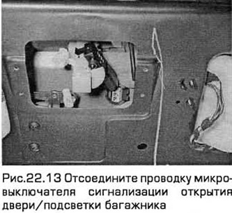
13. Then disconnect the wiring of the door opening alarm microswitch (see Fig. 22.13).
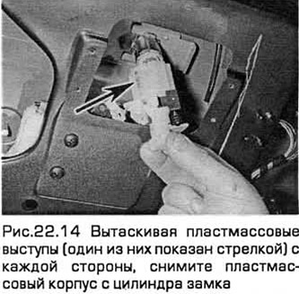
14. By pulling out the plastic tabs on each side, remove the plastic housing from the lock cylinder (see Fig. 22.14).
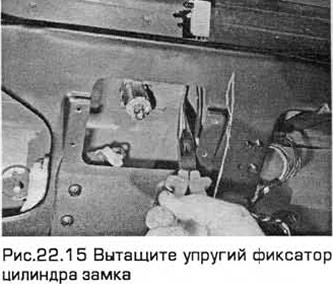
15. Pull out the elastic lock cylinder retainer through the opening in the inner door panel (see Fig. 22.15).
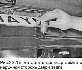
16. Remove the lock cylinder from the outside of the tailgate (see Fig. 22.16).
Castle (Hatchback)
17. Disconnect the negative battery cable.
18. After opening the door to access the lock, pull out the moisture seal. Remove the screws and fasteners and remove the trim panel from the rear of the luggage compartment.
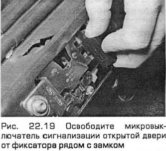
19. Release the door open alarm microswitch from the retainer next to the lock (see Fig. 22.19) and disconnect the wiring from the alarm delay switch. On later models, pull the wiring harness out of the body panel and disconnect the central locking motor wiring connector.
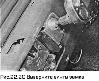
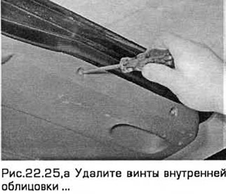
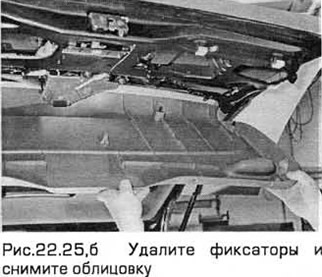
20. Mark the position of the lock screws for subsequent installation. Remove the screws and pull out the lock to access the cable(s) (see Fig. 22.20).
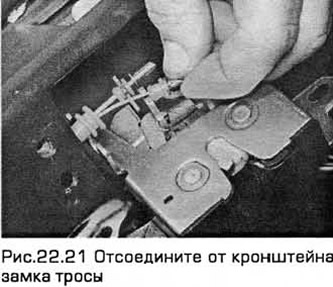
21. Early models have a cable drive for remote opening of the lock, while all models have a cable drive for closing the lock. Disconnect the cable(s) from the lock bracket (see Fig. 22.21).
22. Bend back the plastic edge and remove the central locking drive rod.
23. Remove the lock assembly.
Castle (Universal)
24. Disconnect the negative battery cable.
25. After opening the door, remove the screws and remove the inner lining, releasing it from the fasteners (see Fig. 22.25, a, b).
26. Unscrew the four fastening screws and remove the technological plate. Disconnect the rod from the lock cylinder and (where necessary) from the central locking electric motor (see Fig. 22.12).
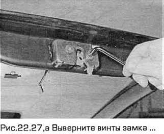
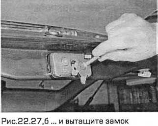
27. Mark the position of the lock screws for subsequent installation. Unscrew the screws and pull out the lock (see Fig. 22.27, a, b).
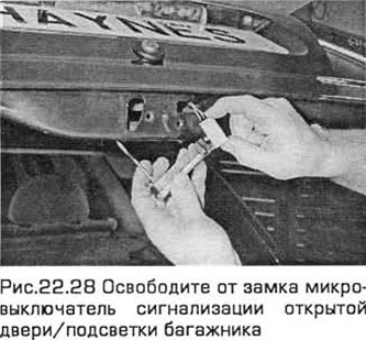
28. Release the open door alarm microswitch from the lock (see Fig. 22.28).
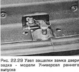
29. If necessary, the lock latch assembly can be removed by disconnecting the cable (early models) and unscrewing the mounting bolts (see Fig. 22.29).
Installation
Lock and lock cylinder - all models
30. Installation - in the reverse order of removal.
The original source of this article can be found at: FORDBOOK.RU