Contents: Removal ↳ Installation ↳
Removal
Lock cylinder - models produced before 1996
1. Disconnect the negative battery cable.
2. After opening the lid, remove the luggage compartment trim from its right corner.
3. Remove the screws and pull the rear light lamp trim out of the guides.
4. Release the door open alarm microswitch from the retainer next to the lock.
5. Pull the cable housing out of the lock bracket. Lift the inner cable until it aligns with the slot in the cylinder lever and disconnect the cable.
6. Pull out the elastic lock retainer.
7. Disconnect the cable support bracket from the cylinder and remove the cylinder.
Lock cylinder - models produced since 1997
8. Disconnect the negative battery cable.
9. After opening the lid, remove the luggage compartment trim from its right corner.
10. Unscrew the nuts located under the light block, fastening the trim panel of the lock cylinder and remove the panel from the outside of the trunk (see Fig. 19.10, a, b).
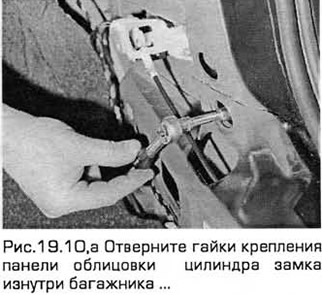
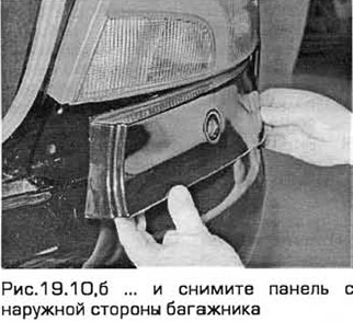
11. From inside the trunk, unscrew the two nuts securing the lock cylinder housing. Then lower the cable bracket and remove the lock cylinder and its housing from outside the trunk (see Fig. 19.11, a, b).
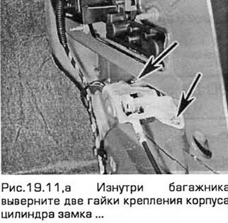
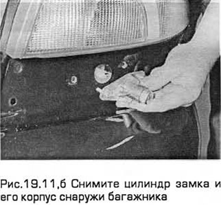
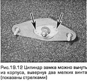
12. The lock cylinder can be removed from the housing by unscrewing two small screws (see Fig. 19.12).
Lock
13. Disconnect the negative battery cable.
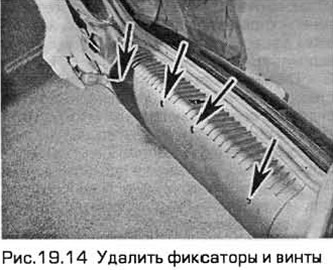
14. After opening the cover, remove the fasteners and screws and remove the trim panels surrounding the lock (see Fig. 19.14).
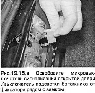
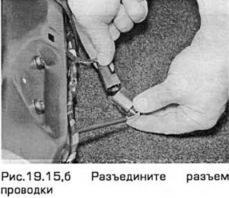
15. Release the open door alarm microswitch from the retainer next to the lock. Disconnect the wiring from the switch (if any) of the alarm delay. On late production models, pull the wiring harness out of the body panel and disconnect the microswitch connector (see Fig. 19.15,a,b).
16. Mark the position of the lock. Unscrew the lock mounting screws and pull out the lock (see Fig. 19.16).

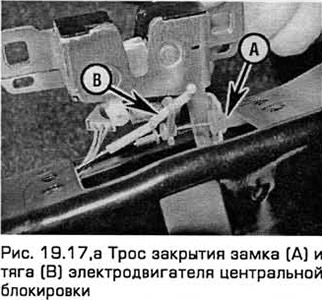
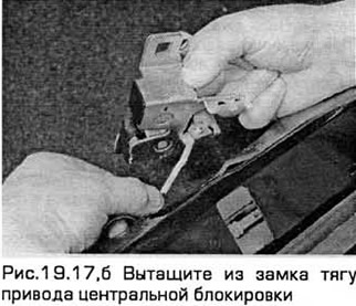
17. Early models have a cable drive for remote lock opening, and all models have a cable drive for lock closing. Disconnect the cable and its sheath from the lock bracket. Bend back the plastic edge and pull out the central locking drive rod (if available) (see Fig. 19.17, a, b).
18. Remove the lock assembly.
Installation
Lock and lock cylinder
19. Installation - in the reverse order of removal. Install the lock according to the marks.