Contents: Electronic unit ↳ Front wheel speed sensor ↳ Rear wheel speed sensor ↳ Brake pedal travel sensor ↳
Removal
1. Disconnect the negative battery cable.
2. Wipe the surfaces around the filler cap of the tank, and then remove the cap. Remove the liquid from the tank with a syringe, or by opening the air bleed nipple and pumping the liquid out of it into another container.
3. On vehicles manufactured after 1998: Remove the relay located above the hydraulic block. The relay simply slides off the clips, also remove the wiring cover and relay support bracket.
4. Place a rag under the connections to prevent fluid from leaking from the disconnected tubes.
5. Mark the location of each tube, unscrew the connecting nuts and disconnect the tubes from the block. Disconnect the low pressure drain pipes as well (see figure 21.5,a,6).
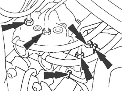
Figure 21.5,a. Brake pipe connections on the ABS system hydraulic unit.
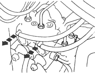
Figure 21.5,b. Disconnect the low pressure drain pipes from the ABS system hydraulic unit.
Installation
6. Installation is carried out in reverse order of removal. After completing the installation, bleed the brake system (see point 2)
Electronic unit
Removal
7. Disconnect the negative battery cable.
8. Release the fastener and the housing on which the unit is installed.
9. Disconnect the unit and slide it out of the housing (see Fig. 21.9).
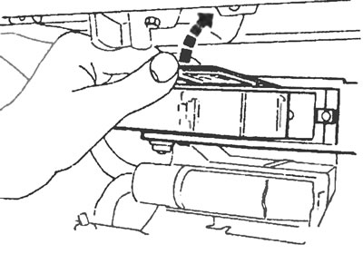
Figure 21.9. Disconnect the ABS electronic unit and remove it from the housing.
10. Disconnect the electrical wiring plug and remove the unit.
Installation
11. Installation is carried out in the reverse order of removal.
Front wheel speed sensor
Removal
12. Apply the parking brake, loosen the front wheel nuts, then raise the front of the vehicle and support it on jack stands. Remove the front wheels.
13. Disconnect the sensor wire from the electrical wiring (see figure 21.13).
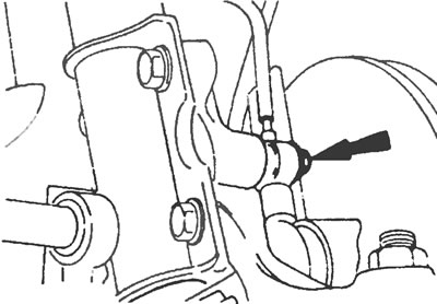
Figure 21.13. Unscrew the bolt (marked with an arrow) and remove the front ABS wheel speed sensor from the steering knuckle.
14. Loosen the bolt and remove the sensor from the steering knuckle. Remove the sensor along with the vehicle wire.
Installation
15. Installation is carried out in the reverse order of removal. When installing the sensor, make sure that the mating surfaces are clean and free of oil. Check that the sensor mounting tab is installed correctly. Pull the wire through the wheel arch and secure it with all the provided clamps. After securing the sensor, turn the steering wheel from lock to lock and make sure there is no friction between the sensor wire and the wheel or suspension, then lower the vehicle to the ground.
Rear wheel speed sensor
Removal
16. Place chocks under the front wheels, then jack up the rear of the car and install supports.
17. Disconnect the sensor wire from the electrical wiring.
18. Loosen the bolt and remove the sensor from the brake mechanism protective cover (see figure 21.18). Remove the sensor along with the wire from the vehicle.
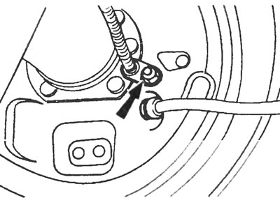
Figure 21.18. Unscrew the bolt (marked with an arrow) fastenings of the rear wheel speed sensor of the ABS system and remove the sensor from the protective cover of the brake mechanism.
Installation
19. Installation is carried out in the reverse order of removal. When inserting the sensor into place, make sure that the mating surfaces are clean and free of oil. Correctly position and secure the wires with all provided clamps.
Brake pedal travel sensor
Removal
20. Disconnect the negative battery cable.
21. Eliminate the vacuum in the vacuum booster by pressing the brake pedal several times; the engine must be turned off.
22. Cut the sensor cable tie and disconnect the wiring plug (see figure 21.22).
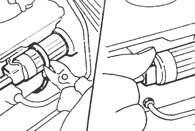
Figure 21.22. Cut the cable tie of the ABS brake pedal travel sensor and disconnect the wiring plug.
23. Remove the lock washer and carefully remove the sensor from the vacuum booster. When doing this, make sure that the sealing ring does not fall inside the amplifier. If this happens, remove it before installing the sensor back.
Installation
24. Installation is carried out in the reverse order of removal. Before installation, make sure the O-ring is in place on the sensor housing and secure the cable to the housing with a new cable tie.