Contents: Introduction ↳ Spare parts for replacement ↳ Special tools ↳ Important precautions ↳ Warnings, cautions, and notes found… ↳ How to use this guide ↳ Examples ↳
Introduction
The Workshop Manual has been written in a new format to meet the needs of Ford technicians worldwide. The ultimate goal is to use common formats and have similar content in every Workshop Manual used worldwide.
This manual contains a general description of the appropriate maintenance and repair work on the vehicle, performed using proven, effective equipment. Following the procedures described will ensure the quality of the work performed.
Spare parts for replacement
Ford and Motorcraft replacement parts are manufactured to the same standards as the original factory-installed components. For this reason, we recommend that you use only genuine Ford or Motorcraft replacement parts for service or repair.
Special tools
The Special Tool(s) Chart preceding each procedure shows all the special tools required to perform the repair. Where possible, illustrations are provided to help identify the special tool required. Special tools can be ordered from Loewener OTC GmbH, Rotunda Equipment or their agents/distributors.
| Europe | North America |
| V Loewener OTC GmbH | Rotunda Equipment |
| Industriestrasse 67 | PO Box 1450 |
| D 40764 Langenfeld | Kenosha W1 53141-1450 |
| Germany | Phone 1-800-ROTUNDA |
| Tel: + 49 (0) 2173 928-0 | Fax: +1-800-762-6181 () |
| Fax: + 49 (0) 2173 928-199 | WWW.FORDROTUNDA.COM |
Important precautions
The use of proper maintenance techniques and the correct execution of repair procedures are important both for the safe, reliable operation of the vehicle itself and for the personal safety of the technician performing the specific job.
This manual cannot fully cover all the options and provide recommendations and warnings for each of them. Therefore, anyone who intends to deviate from the instructions prescribed by this manual must decide for themselves what they are willing to sacrifice: personal safety or the car itself. And based on this, they must select the necessary methods, tools and spare parts.
Warnings, cautions, and notes found in this manual
WARNING: Warnings indicate that injury may result if a procedure is not performed correctly.
CAUTION: Cautions indicate that damage to the vehicle or equipment being used may occur if a procedure is not performed correctly.
NOTE: The purpose of the note is to provide additional important information required to complete the repair completely and satisfactorily.
As you read this manual, you will encounter WARNINGS, CAUTIONS, and NOTES.
If a warning, caution, or note applies to a series of items, it is given at the beginning of the sequence of actions. If it applies to only one item, it precedes that item (is located after the item number).
How to use this guide
The service station manual provides information on service and repair procedures.
This guide is divided into groups and sections. Sections devoted to special systems are collected together in the corresponding group. A group is dedicated to a specific part of the vehicle. This manual is divided into five groups: General Information, Chassis, Powertrain, Electrical Equipment, Body and Paintwork. The group number is the first digit of the section number.
The pages at the beginning of this manual list all the sections available. Each section has a list that explains the contents of the chapters "General Specifications", "Description and Function" and "Service Adjustments and Checks".
If elements need to be removed or disassembled in a certain sequence, they will be indicated in the illustration with corresponding numbers and the accompanying text will be numbered accordingly (refer to the chapter "Examples").
All references to left or right in a vehicle are determined by the driver's position when sitting in the seat and looking forward.
All references to left or right side relating to the engine are determined by the position of the flywheel facing towards the front camshaft pulley.
Instructions on the use of WDS, FDS2000 or STAR Next Generation Diagnostics (NGS) equipment will be provided as needed.
Inspection and verification
Visual inspection charts, symptom charts and other information charts (such as charts containing diagnostic programs), additional test procedures with technical specifications or user direction to a special test procedure.
Table of signs of malfunction
The trouble symptoms table lists the trouble symptoms, the cause of the trouble, and the steps needed to find the cause.
Pinpoint tests
When diagnosing electrical systems, Pinpoint tests are used to determine the source of a problem. Testing is performed in a logical, step-by-step sequence. Pinpoint tests are divided into two columns: "STATES" and "DETAILS/RESULTS/ACTIONS".
The STATUS column is used exclusively for graphical information and pictograms (with or without captions), while the DETAILS/RESULTS/ACTIONS column directs the technician to another check point or contains a description of specific corrective actions.
The numbers in the boxes indicate the sequence in which the described actions should be performed.
Element checks
Element validation is performed when an element is tested in complex/complex pinpoint tests, or when the procedure is too complex to fit into a single pinpoint test page.
Graphic images
Graphic images illustrate the measurement or test to be performed within a given test item.
For voltmeters and ohmmeters, a tester image is used.
When a single graphic representation relates to several measurements, the test leads are first represented by a solid line and then, starting from the point where the leads are divided to illustrate individual measurements, they (the leads) are represented by a broken line.
The splitter box/testers are represented by a test pin in a double circle. The test pins are marked with a pin number.
Examples
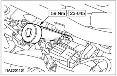
Special tools and tightening torque values Any need to use a special tool will be indicated by a drawing showing how to use the tool and the tool number. Torque values will be given at the appropriate place in the procedure description.
For more information, please visit the website fordbook.ru