|
STATES |
DETAILS/RESULTS/ACTIONS |
|
A1: CHECK THE INTERIOR LIGHT DELAY FUNCTION. |
|
|
1CHECK the interior light delay function. |
|
|
• Does the interior light delay function work correctly? |
|
|
→ Yes |
|
|
Go to A2 |
|
|
→ No |
|
|
CHECK the operation of the General Electronic Module (GEM). Refer to Section 419-10 for additional information. |
|
|
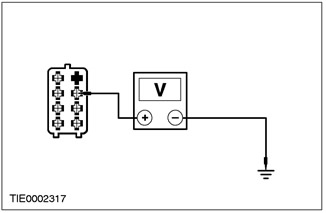
A2: CHECK VOLTAGE SUPPLIED TO OUTSIDE MIRROR CONTROL SWITCH CIRCUIT |
|
|
NOTE:Circuit numbers and wiring colors change at junction point C51 |
|
|
1Disconnect the Outside Mirror Control Switch - C741. |
|
|
2Enter the ON position. |
|
|
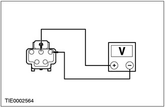
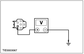
3Measure the voltage between outside mirror control switch pin 6 C741, circuit 29-AD12 (Orange/Yellow), harness side and ground. |
|
• Is the voltage more than 10V? |
|
|
→ Yes |
|
|
Go to A3 |
|
|
→ No |
|
|
REPAIR circuit 29-AD12 (orange/yellow). CHECK system for proper operation. |
|
|
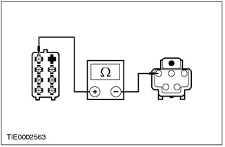
A3: CHECK OUTSIDE MIRROR CONTROL SWITCH GROUND CIRCUIT FOR OPEN |
|
|
NOTE:The chain numbering changes at the solder joint point S197 |
|
|
1Enter the OFF position. |
|

|
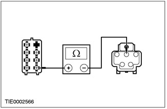
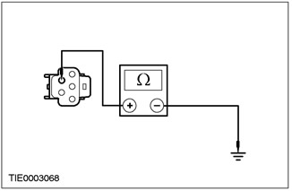
2Measure the resistance between outside mirror control switch pin 4 C741, circuit 31-AD12 (Black), harness side and ground. |
|
• Is the resistance less than 5 ohms? |
|
|
→ Yes |
|
|
Go to A4 |
|
|
→ No |
|
|
REPAIR electrical circuit 31-AD12 (black). CHECK for proper system operation. |
|
|
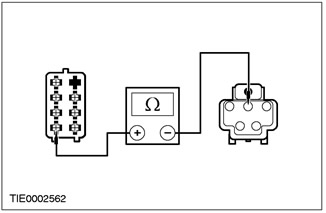
A4: CHECK 32-AD1 (WHITE/RED) CIRCUIT FOR OPEN CIRCUIT |
|
|
NOTE:Circuit numbers and wiring colors change at connection point S200 |
|
|
1Disconnect Driver Side Outside Mirror - C807. |
|

|
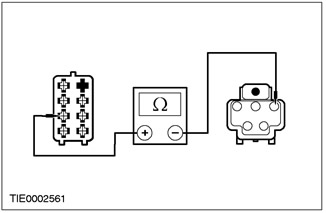
2Measure the resistance between outside mirror control switch C741 pin 3, circuit 32-AD1 (WH/RD), harness side and driver side outside mirror C807 pin 1, circuit 32-AD6 (WH), harness side. |
|
• Is the resistance less than 5 ohms? |
|
|
→ Yes |
|
|
CHECK the validity of the customer's complaint. |
|
|
→ No |
|
|
REPAIR electrical circuit 32-AD1 (white/red). CHECK for proper system operation. |
|
PINPOINT TEST B: ONE MIRROR DOESN'T WORK
|
STATES |
DETAILS/RESULTS/ACTIONS |
|
B1: CHECK FOR BROKEN CONNECTIONS BETWEEN THE OUTSIDE MIRROR CONTROL SWITCH AND THE INOPERATIVE OUTSIDE MIRROR |
|
|
NOTE:The circuit numbers and wiring colors change at connection point S200. |
|
|
1Disconnect Inoperative Outside Mirror - C807 or C808. |
|

|
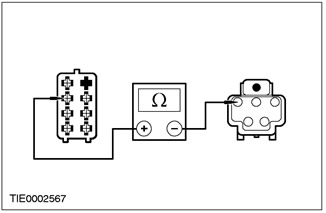
2Measure the resistance between outside mirror control switch pin 3 C741, circuit 32-AD1 (WH/RD), harness side and the inoperative outside mirror: - Driver's side exterior mirror - pin 1 C807, electrical circuit 32-AD6 (white), on the wiring side. - Outside mirror, passenger side - pin 1 C808, electrical circuit 32-AD9 (white/green), wiring side. |
|
• Is the resistance less than 5 ohms? |
|
|
→ Yes |
|
|
INSTALL the new outside mirror. CHECK the system for proper operation. |
|
|
→ No |
|
|
REPAIR circuit 32-AD6 (white) or circuit 32-AD9 (white/green). CHECK for proper system operation. |
|
PINPOINT TEST C: ONE MIRROR DOES NOT WORK ACCORDING TO SWITCH COMMANDS
|
STATES |
DETAILS/RESULTS/ACTIONS |
|
C1: CHECK OUTSIDE MIRROR OPERATION DEPENDING ON SWITCH COMMANDS |
|
|
1Enter the ON position. |
|
|
2PRESS the outside mirror control switch. |
|
|
• Does the outside mirror operate as commanded by the switch? |
|
|
→ Yes |
|
|
CHECK the validity of the customer's complaint. |
|
|
→ No |
|
|
Driver Side Outside Mirror - UP/DOWN Adjustment Not Working Go to C2. Driver's side outside mirror - LEFT/RIGHT adjustment does not work Go to C5. Outside mirror on the passenger side - UP/DOWN adjustment does not work Go to C8. Outside mirror on the passenger side - LEFT/RIGHT adjustment does not work Go to C11. |
|
|
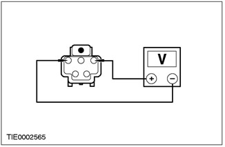
C2: CHECK OUTSIDE MIRROR UP/DOWN ADJUSTMENT CIRCUIT ON DRIVER SIDE |
|
|
NOTE:The circuit numbers and wiring colors change at connection point S200. |
|
|
1Disconnect Driver Side Outside Mirror - C807. |
|
|
2Enter the ON position. |
|
|
3PRESS the outside mirror control switch to select the driver's side outside mirror. |
|

|
4Measure the voltage between driver side outside mirror C807 pin 2, circuit 34-AD7 (BL/RED), harness side and pin 1, circuit 32-AD6 (WH), harness side. - Press the outside mirror control switch to the UP and DOWN positions. |
|
• Does the voltage exceed 10 V when the outside mirror control switch is moved to the UP position and the polarity is reversed when moved to the DOWN position? |
|
|
→ Yes |
|
|
INSTALL the new outside mirror. CHECK the system for proper operation. |
|
|
→ No |
|
|
Go to C3 |
|
|
C3: CHECK ELECTRICAL CIRCUIT 34-AD7 (BLUE/RED) FOR OPEN |
|
|
1Enter the OFF position. |
|
|
2Disconnect the Outside Mirror Control Switch - C741. |
|
|
3Measure the resistance between outside mirror control switch C741 pin 1, circuit 34-AD7 (BL/RED), harness side and outside mirror C807 pin 2, circuit 34-AD7 (BL/RED), harness side. |
|
• Is the resistance less than 5 ohms? |
|
|
→ Yes |
|
|
Go to C4 |
|
|
→ No |
|
|
REPAIR circuit 34-AD7 (blue/red). CHECK system for proper operation. |
|
|
C4: CHECK ELECTRICAL CIRCUIT 32-AD6 (WHITE) FOR OPEN |
|

|
1Measure the resistance between outside mirror control switch pin 3 C741, circuit 32-AD1 (WH/RD), harness side and outside mirror pin 1 C807, circuit 32-AD6 (WH), harness side. |
|
• Is the resistance less than 5 ohms? |
|
|
→ Yes |
|
|
INSTALL the new outside mirror. CHECK the system for proper operation. |
|
|
→ No |
|
|
REPAIR circuit 32-AD6 (white). CHECK for proper system operation. |
|
|
C5: CHECK LEFT/RIGHT TURN CIRCUIT OF DRIVER SIDE OUTSIDE MIRROR |
|
|
NOTE:Circuit numbers and wiring colors change at connection point S200 |
|
|
1Disconnect Driver Side Outside Mirror - C807. |
|
|
2Enter the ON position. |
|
|
3PRESS the outside mirror control switch to select the driver's side outside mirror. |
|
|
4Measure the voltage between C807 pin 3 outside mirror, circuit 33-AD8 (Yellow/Blue), harness side and C807 pin 1, circuit 32-AD6 (White), harness side. - PRESS the outside mirror control switch to the LEFT and RIGHT positions. |
|
• Does the voltage exceed 10 V when the outside mirror control switch is moved to the LEFT position, and the polarity is reversed when moved to the RIGHT position? |
|
|
→ Yes |
|
|
INSTALL the new outside mirror. CHECK the system for proper operation. |
|
|
→ No |
|
|
Go to C6 |
|
|
C6: CHECK ELECTRICAL CIRCUIT 33-AD8 (YELLOW/BLUE) FOR OPEN CIRCUIT |
|
|
1Enter the OFF position. |
|
|
2Disconnect the Outside Mirror Control Switch - C741. |
|
|
3Measure the resistance between outside mirror control switch pin 7 C741, circuit 33-AD8 (YE/BL), harness side and outside mirror control switch pin 3 C807, circuit 33-AD8 (YE/BL), harness side. |
|
• Is the resistance less than 5 ohms? |
|
|
→ Yes |
|
|
Go to C7 |
|
|
→ No |
|
|
REPAIR circuit 33-AD8 (yellow/blue). CHECK system for proper operation. |
|
|
C7: CHECK ELECTRICAL CIRCUIT 32-AD6 (WHITE) FOR OPEN |
|

|
1Measure the resistance between outside mirror control switch pin 3 C741, circuit 32-AD1 (WH/RD), harness side and mirror C807 pin 1, circuit 32-AD6 (WH), harness side. |
|
• Is the resistance less than 5 ohms? |
|
|
→ Yes |
|
|
INSTALL the new outside mirror. CHECK the system for proper operation. |
|
|
→ No |
|
|
REPAIR circuit 32-AD6 (white). CHECK for proper system operation. |
|
|
C8: CHECK PASSENGER SIDE MIRROR UP/DOWN ADJUSTMENT CIRCUIT |
|
|
NOTE:The circuit numbers and wiring colors change at connection point S200. |
|
|
1Disconnect the Passenger Side Outside Mirror - C808. |
|
|
2Enter the ON position. |
|
|
3Measure the voltage between pin 2 C808 outside mirror, circuit 34-AD10 (BL/YE), harness side and pin 1 C808, circuit 32-AD9 (WH/GN), harness side. - PRESS the outside mirror control switch in the UP and DOWN positions. |
|
• Does the voltage exceed 10 V when the outside mirror control switch is moved to the UP position and the polarity is reversed when moved to the DOWN position? |
|
|
→ Yes |
|
|
INSTALL the new outside mirror. CHECK the system for proper operation. |
|
|
→ No |
|
|
Go to C9 |
|
|
C9: CHECK ELECTRICAL CIRCUIT 34-AD10 (BLUE/YELLOW) FOR OPEN |
|
|
1Enter the OFF position. |
|
|
2Disconnect the Outside Mirror Control Switch - C741. |
|
|
3Measure the resistance between outside mirror control switch pin 2 C741, circuit 34-AD10 (BL/YE), harness side and outside mirror pin 2 C808, circuit 34-AD10 (BL/YE), harness side. |
|
• Is the resistance less than 5 ohms? |
|
|
→ Yes |
|
|
Go to C10 |
|
|
→ No |
|
|
REPAIR circuit 34-AD10 (blue/yellow). CHECK system for proper operation. |
|
|
C10: CHECK 32-AD9 (WHITE/GREEN) CIRCUIT FOR OPEN |
|
|
1Measure the resistance between outside mirror control switch pin 3 C741, circuit 32-AD1 (WH/RD), harness side and outside mirror pin 1 C808, circuit 32-AD9 (WH/GN), harness side. |
|
• Is the resistance less than 5 ohms? |
|
|
→ Yes |
|
|
INSTALL a new mirror. CHECK that the system is working correctly. |
|
|
→ No |
|
|
REPAIR circuit 32-AD9 (white/green). CHECK for proper system operation. |
|
|
C11: CHECK LEFT/RIGHT TURN CIRCUIT OF PASSENGER SIDE OUTSIDE MIRROR |
|
|
NOTE:Circuit numbers and wiring colors change at connection point S200 |
|
|
1Disconnect Passenger Side Mirror - C808. |
|
|
2Enter the ON position. |
|

|
3Measure the voltage between pin 3 C808 outside mirror, circuit 33-AD11 (YE/PUP), harness side and pin 1 C808, circuit 32-AD9 (WH/GN), harness side. - PRESS the outside mirror control switch to the LEFT and RIGHT positions. |
|
• Does the voltage exceed 10 V when the outside mirror control switch is moved to the LEFT position, and the polarity is reversed when moved to the RIGHT position? |
|
|
→ Yes |
|
|
INSTALL the new outside mirror. CHECK the system for proper operation. |
|
|
→ No |
|
|
Go to C12 |
|
|
C12: CHECK CIRCUIT 33-AD11 (YELLOW/PURPLE) FOR OPEN |
|
|
1Enter the OFF position. |
|
|
2Disconnect the Outside Mirror Control Switch - C741. |
|
|
3Measure the resistance between outside mirror control switch pin 5 C741, circuit 33-AD11 (YE/VIEW), harness side and outside mirror pin 3 C808, circuit 33-AD11 (YE/VIEW), harness side. |
|
• Is the resistance less than 5 ohms? |
|
|
→ Yes |
|
|
Go to C13 |
|
|
→ No |
|
|
REPAIR circuit 33-AD11 (yellow/purple). CHECK system for proper operation. |
|
|
C13: CHECK 32-AD9 (WHITE/GREEN) CIRCUIT FOR OPEN |
|

|
1Measure the resistance between outside mirror control switch pin 3 C741, circuit 32-AD1 (WH/RD), harness side and outside mirror pin 1 C808, circuit 32-AD9 (WH/GN), harness side. |
|
• Is the resistance less than 5 ohms? |
|
|
→ Yes |
|
|
INSTALL the new outside mirror. CHECK the system for proper operation. |
|
|
→ No |
|
|
REPAIR circuit 32-AD9 (White/Red). CHECK system for proper operation. |
|
PINPOINT TEST D: HEATED OUTSIDE MIRROR DOES NOT DE-ICE
|
STATES |
DETAILS/RESULTS/ACTIONS |
|
D1: CHECK THE OPERATION OF THE REAR WINDOW HEATING |
|
|
1The ignition is on. |
|
|
2Press the rear window defroster switch |
|
|
• Is the rear window defroster functioning properly? |
|
|
→ Yes |
|
|
Go to D2 |
|
|
→ No |
|
|
REPAIR the rear window defroster. Refer to Section 501-11 for additional information. |
|
|
D2: CHECK THE VOLTAGE SUPPLIED TO THE INOPERATIVE OUTSIDE MIRROR |
|
|
1Enter the OFF position. |
|
|
2Disconnect Inoperative Outside Mirror - C807 or C808. |
|
|
3Enter the ON position. |
|
|
4PRESS the rear window defroster switch. |
|
|
5Measure the voltage between: – pin 4 C807 of the driver's side exterior mirror, electrical circuit 15S-HB35 (green/black), on the wiring side, and ground. – pin 4 C808 of the passenger side exterior mirror, electrical circuit 15S-HB36 (green/orange), on the wiring side, and ground. |
|
• Is the voltage more than 10V? |
|
|
→ Yes |
|
|
Go to D3 |
|
|
→ No |
|
|
REPAIR circuit 15S-HB35 (green/black) or circuit 15S-HB36 (green/orange). CHECK system operation for proper operation. |
|
|
D3: CHECK THE GROUND CIRCUIT OF THE INOPERATIVE OUTSIDE MIRROR FOR OPEN |
|
|
1Enter the OFF position. |
|
|
2Measure the resistance between: – pin 5 C807 of the outside mirror on the driver's side, electrical circuit 31-HB35 (black), on the wiring side, and "ground". – pin 5 C808 of the passenger side exterior mirror, electrical circuit 31-HB36 (black), on the wiring side, and ground. |
|
• Is the resistance less than 5 ohms? |
|
|
→ Yes |
|
|
INSTALL a new heated outside mirror glass. CHECK that the system is operating correctly. |
|
|
→ No |
|
|
REPAIR circuit 31-HB35 (black) or circuit 31-HB36 (black). CHECK for proper system operation. |
|