Operating principle of the EEC IV control device
The electric fuel pump delivers fuel from the fuel tank through the fuel filter to the jets, which are located on the distribution pipe. The pressure regulator, located on the distribution pipe, maintains a constant pressure in the fuel system depending on the vacuum in the intake pipe (the pressure should be 2.5 bar). Excess fuel flows back into the fuel tank through the return hose. The rapid circulation of the fuel ensures cooling of the jets. The engine sucks in fresh air through the air filter and the intake pipe. A device is installed in the intake pipe, which measures the mass of the sucked-in air using the following principle: an electrically heated coil is cooled by the air sucked in as it passes by. In order to maintain a constant coil temperature, the heating current varies accordingly depending on the density/temperature of the sucked-in air. Based on the fluctuations in the heating current, the control device determines the mass of the sucked-in air. The current position of the throttle valve is used as a comparative value. The control device regulates the amount of fuel injected and the duration of injection according to the air mass and engine speed. If the nozzle is open longer, more fuel is injected. Each nozzle is controlled separately according to the ignition sequence. There is such a special concept: sequential injection. Additional sensors and actuators measure the correct amount of fuel in special driving situations.
The fuel injection system control unit regulates the idle speed using the idle speed control valve. This valve regulates the amount of air at idle speed without the throttle valve being operated. As a result, the idle speed remains constant, regardless of whether additional consumers, such as the power steering or the cooling compressor, are running at the same time.
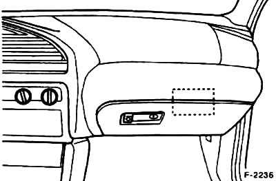
The electrical control unit is located on the right under the instrument panel. The connector can be accessed from the engine compartment after removing the power steering pump receiver. Before disconnecting the connector, the hexagon-head bolt in the connector must be unscrewed.
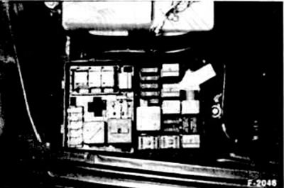
The fuel pump relay supplies current to the fuel pump. A protective circuit stops the current supply as soon as the pulse characterizing the number of revolutions is not received, for example, if the engine stalls. The relay is located in the fuse box in the engine compartment.
The oxygen sensor measures the oxygen content in the exhaust gases and sends corresponding signals to the control unit. The control unit then regulates the injected amount of fuel so that the exhaust gases burn optimally in the catalytic converter.
The intake air temperature sensor measures the temperature of this air, another temperature sensor on the coolant temperature regulator housing measures the temperature of the coolant.
The fuel tank ventilation magnetic valve is controlled depending on the operating state of the engine. The fuel vapors generated in the fuel tank are collected by the activated carbon filter and fed through the combustion valve. The fuel vapors are used by the activated carbon filter and are not released into the surrounding atmosphere.
Inductive sensors are located on the flywheel and camshaft sprocket for the intake cams. They provide information about the current engine speed and crankshaft position to the fuel injection system control unit.
The ignition system has no moving parts, so it does not wear out, with the exception of the spark plugs. If you disconnect the compensation plug in the engine compartment, you can fill the tank with fuel of inferior quality, see chapter "Ignition system". If you fill up again with Super petrol (minimum 96 ROZ), the compensation plug must be reconnected.

The control unit controls the exhaust gas recirculation system and the pulse air system. Both systems reduce the content of harmful substances in the exhaust gases: the pulse air system operates when the engine is hot. Fresh air is added to the exhaust gases in measured doses, which allows the exhaust gases to burn better in the catalytic converter. Exhaust gas recirculation reduces the emission of nitrogen oxides. This is achieved due to the fact that a small portion of the exhaust gases is added back to the intake air. The sensors and valves required for this are located on bracket "1" on the front wall of the engine in the engine compartment. 3 - electronic differential pressure converter; 4 - pulse magnetic valve; 5 - electronic vacuum regulator (2 - ignition control device, only in automatic transmissions, in other cases integrated into the engine control device).
Other functions of the engine control unit: the cooling fan is controlled depending on the engine temperature and (if equipped) whether the air conditioner is on. The automatic transmission shift points are adjusted depending on road conditions.
[The full article is on the online resource fordbook]