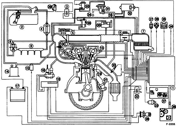
Schematic representation of the fuel injection system in 1.8 and 2.0-liter engines: 1 - EEC IV module; 2 - Fuel pump; 3 - Fuel pump relay; 4 - Fuel filter; 5 - Idle speed control valve (ISC); 6 - Air flow meter (MAF); 7 - Air filter; 8 - Fuel pressure regulator; 9 - Distribution pipe for fuel; 10 - Throttle sensor; 11 - Intake air temperature sensor; 12 - Jet; 13 - Camshaft position sensor; 14 - Tank with activated carbon; 15 - Magnetic valve; 16 - DIS ignition coil; 17 - Battery; 18 - EDIS-4 module; 19 - Coolant temperature sensor; 20 - Oxygen sensor; 21 - Tachometer / crankshaft position sensor; 22 - Power supply relay; 23 - Pressure switch of the power steering pump; 24 - Air conditioning compressor clutch; 25 - Service plug / octane number; 26 - Plug for autotest; 27 - Diagnostic plug for FDS 2000; 28 - Ignition switch; 29 - Safety switch; 30 - Electronic vacuum regulator; 31 - Exhaust gas recirculation valve; 32 - Differential pressure transducer; 33 - Differential pressure measurement point; 34 - To the intake manifold; 35 - Pulse air system filter / valve body; 36 - Magnetic valve of the impulse air system; 37 - Air conditioning/cooling fan connection; 38 - Control/automatic transmission
Visitor comments