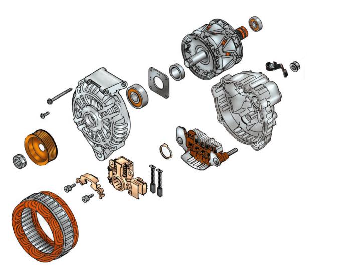
Fig. 10.6. Generator parts: 1 – pulley mounting nut; 2 – pulley; 3 – front bearing pressure plate fastening screw; 4 – generator cover tightening bolt; 5 – drive side cover; 6 – front rotor bearing; 7 – bearing pressure plate; 8 – distance ring; 9 – rotor; 10 – slip rings; 11 – rear rotor bearing; 12 – contact bolt nut; 13 – contact bolt terminal; 14 – cover from the contact ring side; 15 – rectifier block; 16 – sealing gasket; 17 – brushes; 18 – brush holder with voltage regulator; 19 – overlay; 20 – brush holder mounting screws; 21 – stator.
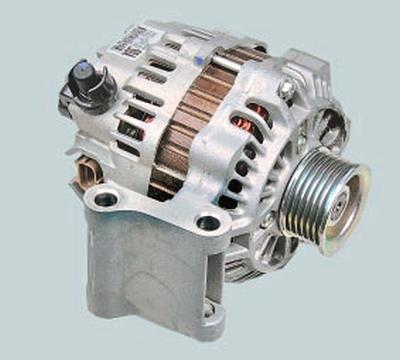
Ford Mondeo vehicles are equipped with three-phase alternating current generators with electromagnetic excitation, with a built-in rectifier unit and electronic voltage regulator.
The generator shaft contains the fan impeller and drive pulley. The shaft is mounted on sealed bearings that do not require additional lubrication throughout their service life. The shaft is driven from the crankshaft pulley by a poly V-belt.
In addition to the electronic regulator built into the generator, the generator operating modes are also controlled by the electronic engine control unit. It automatically increases the generator output voltage at low ambient temperatures for more efficient recharging of the battery, switches off the generator when starting the engine and increases the engine crankshaft speed at idle with a high electrical load on the generator. If any malfunctions occur in the power supply system and when the ignition is turned on with the engine not running, the engine control unit turns on the battery discharge warning lamp.
Covers 5 (Fig. 10.6), 14 and stator 21 are pulled together by four bolts 4. Rotor shaft 9 rotates in closed-type ball bearings 6 and 11.
The generator stator is equipped with a three-phase winding, made according to the "triangle" scheme (phase windings are attached at three points).
The excitation winding is located on the rotor 9. The terminals of the excitation winding are soldered to two copper contact rings 10 installed on the shaft of the rotor 9.
Power is supplied to the excitation winding through two contact brushes 17 and contact rings 10.
The contact brushes are located in the brush holder 18, combined in one housing with the voltage regulator.
The generator connections are shown in the electrical diagrams.
Depending on the engine model, the vehicle may be equipped with generators of different power, but similar in design.
NOTE: Codes of the occurring faults of the electrical supply system are stored in the memory of the electronic engine control unit. They can be read using a scanner at the service.
USEFUL TIP: Recently, many companies have appeared that specialize in repairing imported starters and generators. There, you can diagnose a faulty unit, purchase spare parts for any model of generator (starter), and get qualified advice. If you are not sure that you can repair a generator (starter) yourself, it makes sense to contact a company that will repair these units quickly, efficiently, and, as a rule, at an affordable price. However, on cars with high mileage, it is often more profitable to replace the unit as a whole with a new one than to replace the failed parts.
The original article can be viewed on the portal (FORDBOOK.ru)