You will need: socket heads "13", "24", screwdrivers with flat and Phillips blades, punch, soldering iron, rotor bearing puller, hammer, tester.
1. Remove the generator from the vehicle (see Removing and installing the generator).
2. Mark the relative positions of the generator parts.
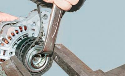
3. Clamp the generator pulley in a vice, having first placed some pads under it or wound an old belt, and unscrew the pulley mounting nut.
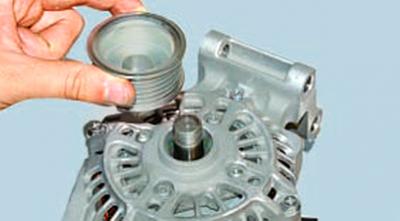
4. Remove the generator pulley from the vice and remove the pulley from the rotor shaft.
NOTE: The generator pulley is secured against turning on the rotor shaft only by friction forces after tightening the fastening nut to the required torque. There is no key in the connection.
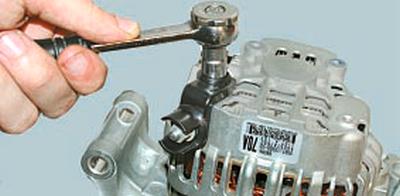
5. Unscrew the nut…
6….and, using a screwdriver, remove the generator terminal.
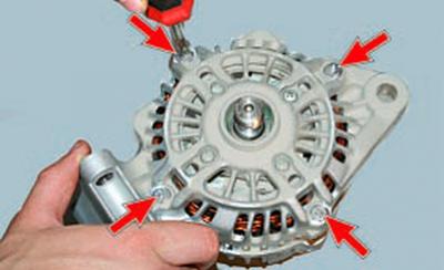
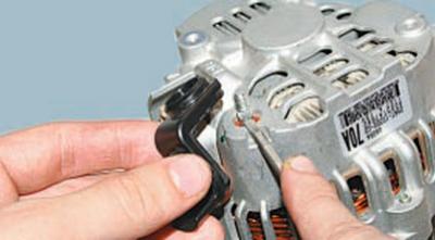
7. Remove the four clamping screws…
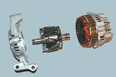
8….pry off the front cover of the generator with a screwdriver and remove the rotor.
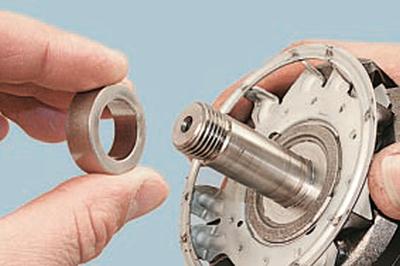
9. Remove the spacer ring from the rotor shaft.
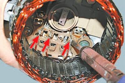
10. Unsolder the three stator winding leads from the rectifier unit and remove the stator.
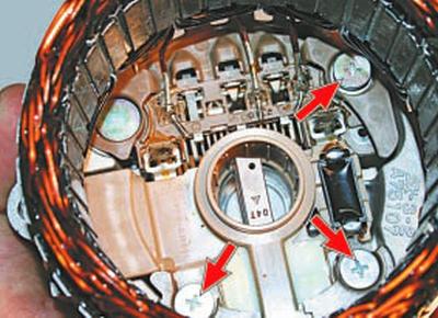
11. From the inside of the cover on the side of the contact rings, unscrew the three fastening screws and remove the brush holder assembled with the rectifier unit and voltage regulator.
NOTE: The stator leads should already be unsoldered from the rectifier unit during stator removal (see item 10).
12. Inspect the generator cover from the drive side. If, when rotating the bearing, you feel play between the races, the inner race rolls or jams, the protective cuffs are damaged or there are grease leaks, replace the bearing. If cracks are found in the cover, especially in the places where the generator is attached, replace the cover.
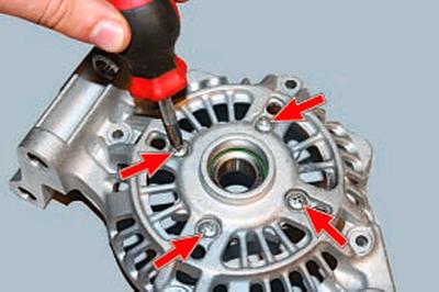
13. To replace the front rotor bearing, remove the four screws securing the pressure plate…
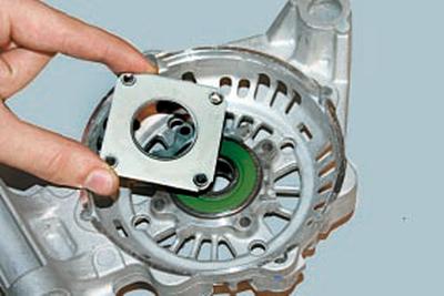
14….and remove the plate.
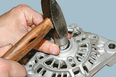
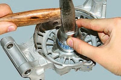
15. Press the bearing out of the cover.
16. Using a mandrel of suitable diameter, press the new bearing into the cover, applying force to the outer race of the bearing.
17. Check the ease of rotation of the bearing from the contact rings. If, when rotating the bearing, there is play between the races, the race rolls or jams, the protective cuffs are damaged or there are grease leaks, replace the bearing. If cracks are found in the cover, replace the cover with a new one.
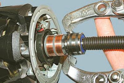
18. Press the bearing off the rotor shaft and install a new bearing, applying force to its inner race with a mandrel of suitable diameter.
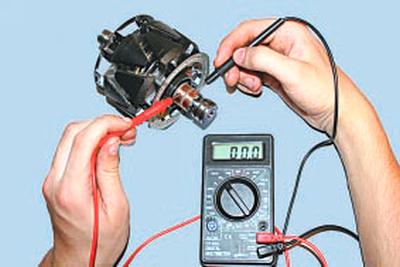
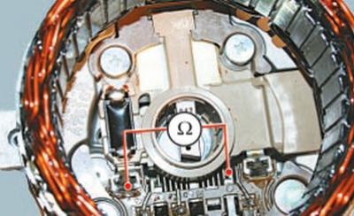
19. Check the rotor winding resistance with a tester by connecting it to the contact rings. The resistance should be approximately 3–5 ohms. If the tester shows infinity, then there is a break in the windings and the rotor must be replaced.
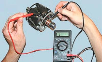
20. Check the rotor winding short circuit to ground. To do this, connect one tester probe to the rotor pole piece and the other one to the contact rings in turn.
The measured resistance should be infinite, otherwise replace the rotor.
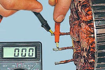
21. Check the stator windings for breakage by measuring the resistance between all winding terminals one by one with a tester. If the measured resistance tends to infinity, the stator must be replaced.
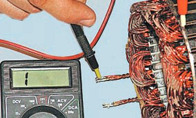
22. Connect the tester probes to the stator housing and to each winding terminal in turn. The measured resistance should be very high (should tend to infinity). Otherwise, replace the stator.
23. Check the rectifier unit. To do this, connect one probe of the tester to the terminal of the phase winding of the stator, and the second probe to the air radiator of the positive diodes. By changing the tester probes, measure the resistance. If the tester readings are the same in both cases, the rectifier unit is faulty and requires replacement.
24. Check the negative diodes in the same way.
25. Check the free protrusion of the brushes. If the brushes protrude from the brush holder by less than 3 mm, replace the brushes or the brush holder assembly.
NOTE: To replace the brushes, you will need to unsolder their wires from the brush holder terminals.
26. Assemble the generator in the reverse order of removal, orienting the generator covers and stator housing according to the previously made marks.
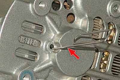
NOTE: Before installing the cover on the rotor slip ring side, recess the brushes and secure them in this position by inserting a pin (such as an unbent paper clip) into the cover hole. Remove the pin after assembly.