


The working system is dual-circuit, with a diagonal connection of the brake mechanisms of the front and rear wheels. One hydraulic drive circuit ensures the operation of the right front and left rear brake mechanisms, the other - the left front and right rear.
If one of the circuits of the service brake system fails, the second circuit is used, ensuring that the vehicle stops with sufficient efficiency.
The hydraulic drive includes a vacuum booster. The car is equipped with an anti-lock braking system (ABS) with electronic stability program (ESP) and hill start assist (HLA) subsystems.
Parking brake system with cable drive on the rear wheel brake mechanisms.
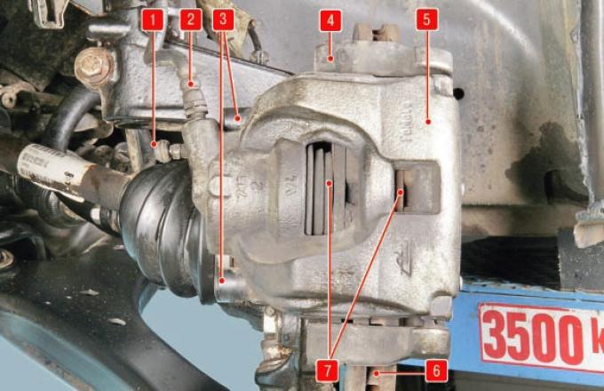
Fig. 9.1. Front wheel brake mechanism: 1 – air release valve; 2 – brake hose; 3 – caliper guide pins; 4 – shoe guide; 5 – brake mechanism support; 6 – brake disc; 7 – brake pads
The front wheel brake mechanism is a ventilated disc with automatic adjustment of the gap between the pads 7 (Fig. 9.1) and the disc 6, with a floating caliper.
The movable bracket is formed by a support 5 with a single-piston working cylinder. The guide 4 of the pads is attached with bolts to the steering knuckle. The movable bracket is fastened with bolts to the guide pins 3 installed in the holes of the guide of the pads. The guide pins are lubricated with consistent grease and protected with plastic bushings. A piston with a sealing ring is installed in the cavity of the working cylinder. Due to the elasticity of this ring, an optimal gap is maintained between the pads and the brake disc, the surface of which is protected by a brake shield. When braking, the piston, under the influence of fluid pressure, presses the inner pad to the disc, as a result of the reaction force, the support moves on the pins and the outer pad is also pressed to the disc, while the pressing force of the pads is the same. When releasing the brakes, the piston is moved away from the pad due to the elasticity of the sealing ring and a small gap is formed between the pads and the disc.
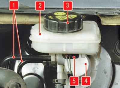
Fig. 9.2. Master brake cylinder: 1 – brake pipes; 2 – master brake cylinder reservoir; 3 – tank cap; 4 – main brake cylinder; 5 – brake fluid level sensor.
The main brake cylinder 4 (Fig. 9.2) of the tandem type of the hydraulic brake drive consists of two separate chambers connected to independent hydraulic circuits. The first chamber is connected to the right front and left rear brake mechanisms, the second - to the left front and right rear.
A reservoir 2 is installed on the master cylinder via rubber connecting bushings, the internal cavity of which is divided by partitions into three sections. Each section supplies one of the chambers of the master brake cylinder and the master cylinder of the clutch release drive (if the car is equipped with a manual gearbox).
When you press the brake pedal, the pistons of the master brake cylinder begin to move, the working edges of the cuffs cover the compensation holes, the chambers and the reservoir are separated and the displacement of the brake fluid begins.
The brake fluid level sensor 5 is installed in the lower half of the tank body. When the fluid level drops below the permissible level, the brake system malfunction indicator lamp lights up in the instrument cluster. Moreover, the lamp is turned on by the electronic control unit of the anti-lock brake system if the signal received from the sensor lasts continuously for at least two seconds. This eliminates the accidental lighting of the indicator lamp when the brake fluid level in the tank fluctuates when driving over uneven roads.
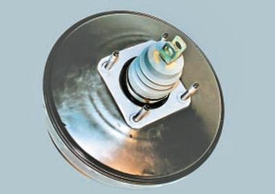
Fig. 9.3. Vacuum amplifier.
The vacuum booster (Fig. 9.3), installed between the pedal mechanism and the main brake cylinder, during braking, due to the vacuum in the engine intake pipe through the rod and piston of the first chamber of the main cylinder, creates additional force proportional to the force from the pedal.
A check valve is installed in the hose connecting the vacuum booster to the engine intake pipe. It maintains the vacuum in the booster if it drops in the intake pipe when the engine operating modes change and after it is stopped.
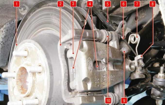
Fig. 9.4. Rear wheel brake mechanism: 1 – brake disc; 2 – shoe guide; 3 – brake mechanism support; 4 – brake pads; 5 – brake hose; 6 – rear parking brake cable; 7 – return spring of the parking brake drive; 8 – parking brake release lever; 9 – air release valve; 10 – caliper guide pins (covered with rubber corrugated covers).
The rear wheel brake mechanism is a disc brake, non-ventilated, with automatic adjustment of the gap between the pads 4 (Fig. 9.4) and the disc 1, with a floating caliper.
The design of the rear wheel brake mechanism is largely similar to the design of the front wheel brake mechanism and differs only in the dimensions of the parts. The main difference is that the rear wheel brake mechanism has a built-in parking brake drive mechanism with a release lever 8, to which the rear cable 6 of the parking brake drive with a release spring 7 is connected.
The movable bracket is formed by a support 3 with a single-piston working cylinder. The guide 2 of the pads is attached with bolts to the rear suspension knuckle. The movable bracket is attached with bolts to the guide pins 10 installed in the holes of the guide of the pads. The guide pins are lubricated with consistent grease and protected by rubber covers. A piston with a sealing ring is installed in the cavity of the working cylinder.
Due to the elasticity of this ring, an optimal gap is maintained between the pads and the brake disc, the surface of which is protected by the brake shield. When braking, the piston, under the influence of fluid pressure, presses the inner pad to the disc, as a result of the reaction force, the caliper moves on the fingers and the outer pad is also pressed to the disc, while the pressing forces of the pads are the same. When releasing the brakes, the piston is moved away from the pad due to the elasticity of the sealing ring, a small gap is formed between the pads and the disc.
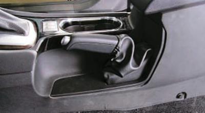
The mechanically operated parking brake consists of a lever mounted on the body base between the front seats, a front cable with an adjusting device and equalizer, to which two rear cables 6 are connected (see Fig. 9.4), and expansion levers 8 installed in the disc brake mechanisms of the rear wheels. The parking brake drive mechanism acts directly on the brake shoes 4 of the service brake mechanism. When moving, the expansion levers move the pistons of the brake cylinders, through them - the inner brake shoes until they stop against the brake discs and then, having received a rigid stop, move the calipers together with the outer shoes, also pressing them against the discs and blocking the discs.
The parking brake does not require special maintenance. During routine maintenance, check the wear of the sector teeth and pawl. If they are worn, replace the parking brake drive lever assembly.
If any breaks in the sheaths or wires are detected, the cables must be replaced with new ones.
The anti-lock braking system (ABS) with the electronic stability program (ESP) and hill start assist (HLA) subsystems is described in Section 13 "Safety systems" (see Active safety system (electronic brake control systems)).
The hydraulic brake system is united into a single unit by metal tubes and hoses. The system is filled with a special brake fluid of a class not lower than DOT-4, which must be replaced periodically. The procedure for replacing the brake fluid is described in the subsection Replacing the brake fluid.
USEFUL TIP: Some drivers, trying to wear out the parking brake cables less, try to use them less often. Such "savings" lead to the opposite result: the cable, rarely moving in the casing, gradually loses mobility, it jams, and eventually breaks. Therefore, use the parking brake in all cases when it is necessary.
If the brake pedal always starts to vibrate when braking, the brake discs are most likely warped. Unfortunately, in this situation, they only need to be replaced, both at the front or back. Periodically appearing and disappearing vibration of the pedal during sharp braking accompanies the operation of the anti-lock braking system and is not a sign of a malfunction.
If the car starts to pull to one side when braking, check the wheel cylinders: they may need to be replaced.
If a knocking noise appears in the front and rear suspensions that disappears when braking, check the tightness of the caliper mounting bolts.
After replacing the brake pads, before starting to move, be sure to press the brake pedal several times - the pistons in the working cylinders should fall into place.