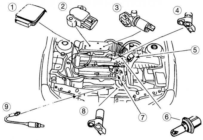
Fig. 142. Location of some units of the 16-valve engine in the engine compartment: 1 — EECV control unit; 2 - throttle position sensor; 3 — idle air control valve; 4 — camshaft position sensor; 5 - air meter; 6 - intake air temperature sensor; 7 - coolant temperature sensor; 8 — crankshaft position sensor; 9 - heated lambda probe
The fuel injection system of a 16-valve engine is shown in Fig. 142.
Coolant temperature sensor continuously informs the control unit of the current coolant temperature. It works on the principle of a temperature-sensitive resistance switch.
Idle speed control valve allows small fluctuations in idle speed to be equalized by the control unit. Therefore, idle speed can be maintained under all load conditions.
Throttle Position Sensor informs the control unit of the current position of the throttle valve.
Lambda probe (oxygen sensor) measures the oxygen content in the exhaust gases, based on this information the EEC V control unit "allows" the operation of the catalytic converter. The sensor starts working only after the operating temperature is reached. It is located in front of the converter in the exhaust gas flow. The sensor is equipped with a heater, which starts working when the ignition is turned on and ensures rapid entry into operation of the converter in the mode with the best operating temperature of 300°C;
Temperature detection sensor incoming air (in the air intake hose).
Air flow meter (mass air flow sensor)) works together with the so-called "hot wire", which measures the mass of the incoming air by changing its resistance. The sensor is located in the air filter housing and can be recognized by the multi-pin plug attached. The "hot wire" constantly has a temperature that is 200°C higher than the air temperature. By maintaining this temperature difference, the air flow is adjusted accordingly.
Camshaft Position Sensor mounted on the front side of the camshaft drive gear, it provides the control unit with information on the first cylinder, which allows fuel injection to be carried out in the required sequence.
Crankshaft position (angle) sensor, informs the control unit of the crankshaft position and controls the flywheel rotation. The flywheel has 36 reference points. At the 90° position before TDC, one of these reference points is missing, which serves as an indication to the control unit for the crankshaft position.
Engine control unit— EEC V.
Nozzles are located directly in front of the cylinder intake valves and are installed in the fuel distributor pipeline. In accordance with the precise calculation of the control unit, each cylinder receives the required portion of fuel in two piston strokes. After the first revolution of the crankshaft, the first half of the fuel portion is injected into the intake air. When the intake valve opens (on a four-cylinder engine, always after two revolutions of the crankshaft), the combustible mixture rushes into the cylinder along with the second half of the portion, which is injected into the air flow.
Fuel pressure regulator. It is located at the end of the fuel distributor line. It functions mechanically using a spring-loaded diaphragm. It regulates the fuel pressure in the injectors. Excess fuel is directed through the fuel outlet line back to the fuel tank.
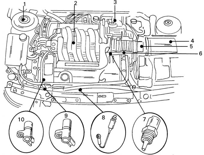
Fig. 143. Location of some V6 engine components in the engine compartment: 1 — EECV control unit; 2 - heated lambda probe, rear; 3 — idle air control valve; 4 - intake air temperature sensor; 5 - air meter; 6 - throttle position sensor; 7 - coolant temperature sensor; 8 - heated lambda probe, front; 9 — crankshaft position sensor; 10 — camshaft position sensor
The main difference of the V6 engine injection system (Fig. 143) is the presence of two lambda probes (front and rear) and six fuel injectors instead of four on the 16-valve engine.