Note: All rear suspension rubber parts are only tightened under load.
Like the front subframe, the rear cross member must be precisely aligned when removed. To do this, coaxial holes are located on the right and left, into which special pins are inserted into the corresponding holes in the bottom of the car. If they are not, then mark the position of the frame cross member before removal.
Removing the rear suspension assembly is carried out as follows:
- loosen the wheel nuts, place the rear of the car on supports and unscrew the wheels;
- Remove the exhaust system, brake hoses and parking brake cables;
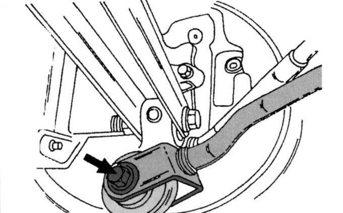
Pic. 210. Fastening jet thrust to the hub
- turn away shown on fig. 210 bolts and nuts on the hub and disconnect the tie rod;
- turn away nuts of fastening of a trailing arm of a suspension bracket to remove draft of the stabilizer of cross-section stability, remove rubber plugs from drafts;
- in the presence of ABS, disconnect both wheel speed sensors;
- Turn away bolts and nuts of the longitudinal lever from a nave and disconnect levers of an independent suspension bracket;
- place a jack under the frame cross member so that it does not fall and compress both rear springs with a suitable coupler;
- unscrew shock-absorber racks from above;
- check that the frame cross member is located on the jack, unscrew the four bolts, slowly lower the cross member;
- unscrew the two bolts and remove the mounting collars of the stabilizer, remove the rubber bushings from the stabilizer;
- unscrew the nuts and bolts and remove both trailing arms from the crossmember, trailing arms use eccentric bolts and washers (for adjusting the rear wheels);
Note: Before dismantling this connection, mark it properly so that it will be installed in the same position during reassembly. Pay attention to which side the bolts are inserted.
Check all parts carefully before assembly. Follow the instructions as you assemble the suspension. Tighten connections without rubber bushings immediately. All self-locking nuts must be replaced with new ones. Assemble and install the rear suspension as follows:
- insert the front trailing arm into the frame cross member, install the bolts from the desired side and tighten the nuts to a torque of 85 Nm;
- insert the rear trailing arm into the frame cross member, install the eccentric bolts and nuts in the previously marked position and tighten the nuts to a torque of 85 Nm;
- fasten the stabilizer to the cross member with rubber bushings and clamps, tighten both bolts to a torque of 23 Nm;
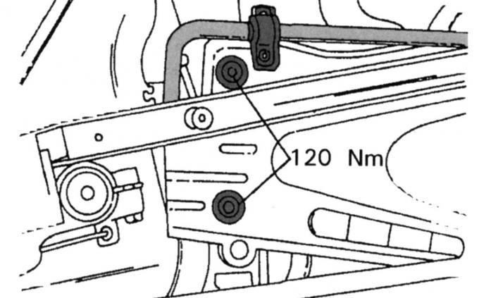
Pic. 211. Bolts of fastening of a cross member of a frame (two bolts are not visible - they are on the other side)
- Jack up the cross member to the required height and precisely align it with the marked marks, tighten the four bolts (two of them are shown in Fig. 211) and screw in with a torque of 120 Nm;
- attach both trailing arms to the hub, the tightening torques are different here: for the bolts and nuts of the front arm - 85 Nm, for the rear arm - 120 Nm;
- if available, install the ABS sensors and tighten them to a torque of 10 Nm;
- insert the stabilizer links with embedded rubber bushings through the front trailing arms and tighten the nuts from the reverse side with a torque of 35 Nm;
- Connect the jet rods to the hubs and tighten the connections to 120 Nm;
- Establish system of release of the fulfilled gases;
- lower the car to the ground and tighten the wheels to 85 Nm;
- Place the car on a lifting platform, then tighten the rubber suspension support parts to the tightening torques indicated above. Check rear wheel alignment and adjust if necessary or have this work done by a workshop.
Visitor comments