|
STATES |
DETAILS/RESULTS/ACTIONS |
|
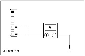
A1: CHECK THE VOLTAGE SUPPLIED TO THE AUDIO UNIT |
|
|
1Disconnect Audio Unit C443. |
|
|
2Enter the ACCESSORY position. |
|
|
3Using a digital multimeter, measure the voltage between C443 pin 1 of the audio unit, circuit 29-MD15 (orange/black), harness side and ground, and between C443 pin 3 of the audio unit, circuit 75-MD15 (yellow/green), harness side and ground. |
|
• Is the voltage greater than 10 V in all cases? |
|
|
→ Yes |
|
|
Go to A2. |
|
|
→ No |
|
|
REPAIR circuit 29-MD15 (orange/black) or circuit 75-MD15 (yellow/green). CHECK for proper system operation. |
|
|
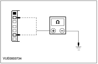
A2: CHECK THE AUDIO UNIT GROUND CIRCUIT FOR OPEN CIRCUITS |
|
|
1Enter the OFF position. |
|
|
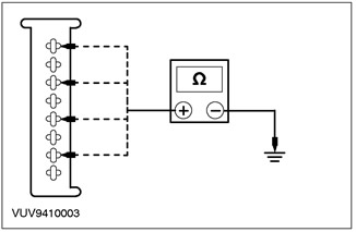
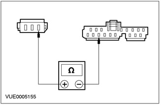
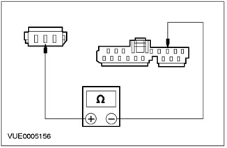
2Using a digital multimeter, measure the resistance between pin 6 of the audio unit C443, circuit 91-MD15 (Black/Green), harness side and ground, and between pin 2 of the audio unit C443, circuit 91-MD34 (Black/Yellow), harness side and ground. |
|
• Is the resistance less than 5 ohms in all cases? |
|
|
→ Yes |
|
|
INSTALL the new audio unit. CHECK the system for proper operation. |
|
|
→ No |
|
|
REPAIR circuit 91-MD15 (Black/Green) or 91-MD34 (Black/Yellow). CHECK for proper system operation. |
|
PINPOINT TEST B: POOR RECEPTION QUALITY
|
STATES |
DETAILS/RESULTS/ACTIONS |
|
B1: CHECK THE ANTENNA CABLE SHIELD |
|
|
1Enter the OFF position. |
|
|
2Enter the OFF position. |
|
|
3Disconnect the Antenna Cable. |
|
|
4Disconnect the antenna cable from the audio unit. |
|
|
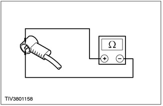
5Using a digital multimeter, measure the resistance between the antenna cable ground connector (shield) and ground. |
|
• Is the resistance less than 1 ohm? |
|
|
→ Yes |
|
|
Go to B2. |
|
|
→ No |
|
|
CLEAN and TIGHTEN the audio unit housing ground and the antenna base to body connection. If the fault is not corrected, INSTALL a new antenna cable. CHECK the system for proper operation. |
|
|
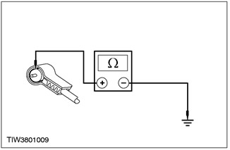
B2: CHECK CENTER ANTENNA WIRE FOR OPEN CIRCUIT |
|
|
1Remove the antenna match. |
|
|
2Using a digital multimeter, measure the resistance on the center wire between the ends of the antenna cable. |
|
• Is the resistance less than 1 ohm? |
|
|
→ Yes |
|
|
Go to B3. |
|
|
→ No |
|
|
INSTALL a new antenna cable. CHECK that the system is operating correctly. |
|
|
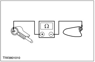
B3: CHECK ANTENNA CABLE FOR SHORT CIRCUIT |
|
|
1Using a digital multimeter, measure the resistance between the antenna center wire and the antenna ground (shield). |
|
• Is the resistance greater than 10,000 ohms? |
|
|
→ Yes |
|
|
CLEAN and TIGHTEN the ground connections at the antenna base, on the audio unit housing and the battery ground wire to the body. If the problem persists, INSTALL a new audio unit. CHECK the system for proper operation. |
|
|
→ No |
|
|
INSTALL a new antenna cable. CHECK that the system is operating correctly. |
|
PINPOINT TEST C: DISTORTION OF SOUND FROM ONE OR MORE SPEAKERS (NOT ALL SPEAKERS)
|
STATES |
DETAILS/RESULTS/ACTIONS |
|
C1: CHECK THE SPEAKER RESISTANCE |
|
|
1Disconnect the non-working speaker. |
|
|
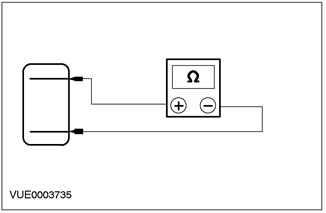
2Using a digital multimeter, measure the resistance between pin 1 and pin 2 of the non-working speaker on the component side. |
|
• Is the resistance approximately 4.0 ohms? |
|
|
→ Yes |
|
|
Go to C2. |
|
|
→ No |
|
|
INSTALL the new speaker. CHECK the system for proper operation. |
|
|
C2: CHECK SPEAKER INPUT FOR SHORT TO GROUND" |
|
|
1Disconnect Audio Unit C443. |
|
|
2Using a digital multimeter, measure the resistance between pin 1 of the non-working speaker connector on the wiring side and ground. |
|
• Is the resistance greater than 10,000 ohms? |
|
|
→ Yes |
|
|
Go to C3. |
|
|
→ No |
|
|
REPAIR the speaker input circuit. CHECK the system for proper operation. |
|
|
C3: CHECK SPEAKER RETURN CIRCUIT FOR SHORT TO GROUND" |
|
|
1Using a digital multimeter, measure the resistance between pin 2 of the non-working speaker connector on the wiring side and ground. |
|
• Is the resistance greater than 10,000 ohms? |
|
|
→ Yes |
|
|
INSTALL a new speaker. CHECK the system for proper operation. If the problem persists, INSTALL a new audio unit. CHECK the system for proper operation. |
|
|
→ No |
|
|
REPAIR the speaker return circuit. CHECK the system for proper operation. |
|
PINPOINT TEST D: NO SOUND FROM ALL SPEAKERS
|
STATES |
DETAILS/RESULTS/ACTIONS |
|
D1: CHECK SPEAKER INPUT CIRCUIT FOR SHORT TO GROUND" |
|
|
1Enter the OFF position. |
|
|
2Disconnect Audio Unit - C442. |
|
|
3Using a digital multimeter, measure the resistance between the following audio unit connector pins and ground: - (Front left speaker) pin 1 C442, circuit 8-MD10 (white/black), harness side and ground. - (Rear left speaker) pin 3 C442, electrical circuit 8-MD11 (white/green), from the wiring side and "ground". - (Front right speaker) pin 5 C442, electrical circuit 8-MD17 (white/red), from the wiring side and "ground". - (Rear right speaker) pin 7 C442, electrical circuit 8-MD18 (white), from the wiring side and "ground". |
|
• Is the resistance greater than 10,000 ohms in all cases? |
|
|
→ Yes |
|
|
Go to D2. |
|
|
→ No |
|
|
REPAIR the circuit concerned. CHECK the system for proper operation. |
|
|
D2: CHECK SPEAKER RETURN CIRCUIT FOR SHORT TO GROUND" |
|
|
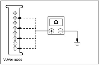
1Using a digital multimeter, measure the resistance between the following audio unit connector pins and ground: - (Front left speaker) pin 2 C442, electrical circuit 10-MD10 (gray/black), wiring side and ground. - (Rear left speaker) pin 4 C442, electrical circuit 10-MD11 (gray/white), from the wiring side and "ground". - (Front right speaker) pin 6 C442, electrical circuit 10-MD17 (gray/red), wiring side and ground. - (Rear right speaker) pin 8 C442, electrical circuit 10-MD18 (gray), from the wiring side and "ground". |
|
• Is the resistance greater than 10,000 ohms in all cases? |
|
|
→ Yes |
|
|
INSTALL the new audio unit. CHECK the system for proper operation. |
|
|
→ No |
|
|
REPAIR the circuit concerned. CHECK the system for proper operation. |
|
PINPOINT TEST E: NO SOUND IN ONE OR MORE SPEAKERS
|
STATES |
DETAILS/RESULTS/ACTIONS |
|
E1: CHECK SPEAKER RESISTANCE |
|
|
1Disconnect the non-working speaker. |
|
|
2Using a digital multimeter, measure the resistance between pin 1 and pin 2 of the non-working speaker on the component side. |
|
• Is the resistance approximately 4.0 ohms? |
|
|
→ Yes |
|
|
Go to E2. |
|
|
→ No |
|
|
INSTALL new speaker(s). CHECK system for proper operation. |
|
|
E2: CHECK THE RESISTANCE IN THE SPEAKER CIRCUIT WITH THE SPEAKER DISCONNECTED |
|
|
1Disconnect Audio Unit - C442. |
|
|
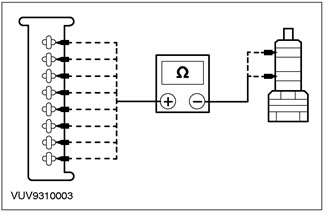
2Using a digital multimeter, measure the resistance between the audio block, C442, and the speaker connector pins corresponding to the non-working speaker(s). - (Front left speaker) pin 1 C442, circuit 8-MD10 (white/black), harness side, and pin 2 C937, circuit 8-MD28 (white), harness side. - (Front left speaker) pin 2 of C442, circuit 10-MD10 (gray/black), harness side, and pin 1 of C937, circuit 10-MD28 (gray), harness side. - (Front right speaker) pin 5 C442, circuit 8-MD17 (white/red), harness side, and pin 2 C938, circuit 8-MD28 (white), harness side. - (Front right speaker) pin 6 C442, circuit 10-MD17 (gray/red), harness side, and pin 1 C938, circuit 10-MD28 (brown), harness side. - (Rear left speaker) pin 3 C442, circuit 8-MD11 (white/green), harness side, and pin 2 C939, circuit 8-MD29 (white/green), harness side. - (Rear left speaker) pin 4 C442, circuit 10-MD11 (gray/white), harness side, and pin 1 C939, circuit 10-MD11 (gray/white), harness side. - (Rear right speaker) pin 7 C442, circuit 8-MD18 (white), harness side, and pin 2 C940, circuit 8-MD29 (white/green), harness side. - (Rear right speaker) pin 8 C442, circuit 10-MD18 (gray), harness side, and pin 1 C940, circuit 10-MD29 (gray/white), harness side. |
|
• Is the resistance less than 5 ohms? |
|
|
→ Yes |
|
|
INSTALL a new speaker. CHECK the system for proper operation. If the problem persists, INSTALL a new audio unit. CHECK the system for proper operation |
|
|
→ No |
|
|
REPAIR the circuit concerned. CHECK the system for proper operation. |
|
PINPOINT TEST F: CD CHANGER DOES NOT WORK OR OPERATES FAULTILY
|
STATES |
DETAILS/RESULTS/ACTIONS |
|
F1: CHECK THE SERIES-INSTALLED FUSE |
|
|
1Check the 3-Amp series fuse provided for the CD changer unit. |
|
|
• Is the 3A fuse good? |
|
|
→ Yes |
|
|
Go to F2. |
|
|
→ No |
|
|
INSTALL a new fuse. CHECK the system for proper operation. |
|
|
F2: CHECK WIRING FROM AUDIO UNIT TO CD CHANGER UNIT |
|
|
1Disconnect the CD Changer Unit - C465. |
|
|
2Disconnect the C464 Audio Unit. |
|
|
3Perform a CD changer unit wiring check. For more information, refer to CD changer unit wiring in this section.. |
|
|
• Is the wiring from the audio unit to the CD changer unit in good condition? |
|
|
→ Yes |
|
|
Go to F3. |
|
|
→ No |
|
|
REPAIR or INSTALL new CD changer wiring. CHECK system for proper operation. |
|
|
F3: CHECK THE FUNCTIONING OF THE CD CHANGER UNIT |
|
|
1Replace with a known good unit with a CD changer. |
|
|
2Check the correct operation of the replacement CD changer unit. |
|
|
• Do all functions of the CD changer unit work properly? |
|
|
→ Yes |
|
|
INSTALL a new CD changer unit. For more information, refer to Checking the Components in this section. CHECK that the system is operating correctly. |
|
|
→ No |
|
|
REMOVE the replacement CD changer. INSTALL the original CD changer. INSTALL the new audio unit. CHECK that the system is operating correctly. |
|
PINPOINT TEST G: RADIO REMOTE CONTROL DOES NOT WORK.
|
STATES |
DETAILS/RESULTS/ACTIONS |
|
G1: CHECK THE OPERATION OF THE AUDIO UNIT WITHOUT USING THE REMOTE CONTROL |
|
|
1Activate the audio unit using the remote control. |
|
|
• Does the audio unit work properly without using the remote control? |
|
|
→ Yes |
|
|
Go to G2. |
|
|
→ No |
|
|
INSTALL a new audio unit. For more information, refer to the Audio Unit section in this section. CHECK that the system is operating correctly. |
|
|
G2: CHECK 8-MD26 CIRCUIT FOR OPEN |
|
|
1Disconnect Audio Unit C447. |
|
|
2Disconnect the Radio Remote Control - C437. |
|
|
3Using a digital multimeter, measure the resistance between pin 11 of C447 of the audio unit, circuit 8-MD26 (White/Black) harness side, and pin 1 of C437 of the radio remote control, circuit 8-MD26 (White/Black) harness side. |
|
• Is the resistance less than 5 ohms? |
|
|
→ Yes |
|
|
Go to G3. |
|
|
→ No |
|
|
REPAIR electrical circuit 8-MD26. CHECK for proper system operation. |
|
|
G3: CHECK CIRCUIT 9-MD26 FOR OPEN |
|
|
1Using a digital multimeter, measure the resistance between pin 12 of C447 of the audio unit, circuit 9-MD26 (brown/yellow) harness side, and pin 2 of C437 of the radio remote control, circuit 9-MD26 (brown/yellow) harness side. |
|
• Is the resistance less than 5 ohms? |
|
|
→ Yes |
|
|
INSTALL the new radio remote control. CHECK the system for proper operation. |
|
|
→ No |
|
|
REPAIR circuit 9-MD26 (Brown/Yellow). CHECK system for proper operation. |
|
Checking the elements
Wiring of the CD changer unit
NOTE: Refer to Electrical Schematics, Section 415-00, for diagrams and connection information.
1. Using a multimeter, check the wiring of the CD changer unit, using the following table to connect the meter wires and compare them to the expected values.
|
CD Changer Unit - C465 |
Audio Block - C464 |
Expected value. |
|
Pin 1 |
Pin 1 |
Less than 5 Ohm |
|
Pin 3 |
Pin 3 |
Less than 5 Ohm |
|
Pin 5 |
Pin 5 |
Less than 5 Ohm |
|
Pin 6 |
Pin 6 |
Less than 5 Ohm |
|
Pin 7 |
Pin 7 |
Less than 5 Ohm |
|
Pin 8 |
Pin 8 |
Less than 5 Ohm |
|
Pin 9 |
Pin 9 |
Less than 5 Ohm |
|
Pin 10 |
Pin 10 |
Less than 5 Ohm |
|
Pin 11 |
Pin 11 |
Less than 5 Ohm |
|
Pin 12 |
Pin 12 |
Less than 5 Ohm |
|
CD Changer Unit - C465 |
Negative lead of the multimeter |
|
|
Pin 1 |
"Weight" |
More than 10,000 Ohm |
|
Pin 3 |
"Weight" |
More than 10,000 Ohm |
|
Pin 5 |
"Weight" |
More than 10,000 Ohm |
|
Pin 6 |
"Weight" |
More than 10,000 Ohm |
|
Pin 7 |
"Weight" |
More than 10,000 Ohm |
|
Pin 8 |
"Weight" |
More than 10,000 Ohm |
|
Pin 9 |
"Weight" |
More than 10,000 Ohm |
|
Pin 10 |
"Weight" |
More than 10,000 Ohm |
|
Pin 11 |
"Weight" |
More than 10,000 Ohm |
|
Pin 12 |
"Weight" |
More than 10,000 Ohm |
2. If the transition to this point occurred from a Pinpoint test, return to this Pinpoint test
The original source of the publication is on the website FordBook