


NOTE: Use a digital multimeter to make all electrical measurements.
PINPOINT TEST A: POWER SEAT DOES NOT WORK
|
STATES |
DETAILS/RESULTS/ACTIONS |
|
A1: CHECK VOLTAGE TO POWER SEAT SWITCH |
|
|
1Enter the OFF position. |
|
|
2Disconnect the Inoperative Power Seat Switch. |
|
|
3Enter the ON position. |
|
|
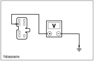
4Measure the voltage between: NOTE:Power Driver's Seat - LHD. - pin 2 C715 of the power seat switch, electrical circuit 29-AH6 (orange/yellow), on the wiring side, and ground. NOTE:Power Driver Seat - RHD - Vehicles built before 12/1999. - pin 2 C716 of the power seat switch, electrical circuit 29-AH14 (orange/yellow), on the wiring side, and ground. NOTE:Power Driver's Seat - RHD - Vehicles built from 01/2000. - pin 2 C715 of the power seat switch, electrical circuit 29-AH6 (orange/yellow), on the wiring side, and ground. |
|
• Is the voltage more than 10V? |
|
|
→ Yes |
|
|
Go to A2. |
|
|
→ No |
|
|
REPAIR circuit 29-AH6 (orange/yellow) or circuit 29-AH14 (orange/yellow). CHECK for proper system operation. |
|
|
A2: CHECK POWER SEAT SWITCH GROUND CIRCUIT FOR OPEN |
|
|
1Enter the OFF position. |
|
|
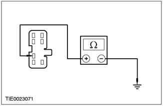
2Measure the resistance between: NOTE:Power Driver's Seat - LHD. - pin 3 C715 of the power seat switch, electrical circuit 31-AH6 (black), on the wiring side, and ground. NOTE:Power Driver Seat - RHD - Vehicles built before 12/1999. - pin 3 C716 of the power seat switch, electrical circuit 31-AH14 (black), on the wiring side, and ground. NOTE:Power Driver's Seat - RHD - Vehicles built from 01/2000. - pin 3 C715 of the power seat switch, electrical circuit 31-AH6 (black), on the wiring side, and ground. |
|
• Is the resistance less than 5 ohms? |
|
|
→ Yes |
|
|
Go to A3. |
|
|
→ No |
|
|
REPAIR circuit 31-AH6 (black) or circuit 31-AH14 (black). CHECK for proper system operation. |
|
|
A3: CHECK THE VOLTAGE IN THE LOWERING CIRCUIT SUPPLIED TO THE POWER SEAT HEIGHT ADJUSTMENT MOTOR |
|
|
1Connect the Inoperative Power Seat Switch. |
|
|
2Disconnect the non-operating power seat height adjustment motor. |
|
|
3Enter the ON position. |
|
|
4Press the power seat switch to the DOWN position. |
|
|
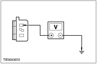
5Measure the voltage between: NOTE:Power Driver Seat - LHD - pin 1 C761 of the electric seat height adjustment motor with electric drive, electrical circuit 32-AH10 (white/black), on the wiring side, and "ground". NOTE:Power Driver Seat - RHD - Vehicles built before 12/1999. - pin 1 C760 of the electric seat height adjustment motor with electric drive, electrical circuit 32-AH18 (white/black), on the wiring side, and "ground". NOTE:Power Driver's Seat - RHD - Vehicles built from 01/2000. - pin 1 C761 of the electric seat height adjustment motor with electric drive, electrical circuit 32-AH10 (white/black), on the wiring side, and "ground". |
|
• Is the voltage more than 10V? |
|
|
→ Yes |
|
|
Go to A4. |
|
|
→ No |
|
|
REPAIR circuit 32-AH10 (white/black) or circuit 32-AH18 (white/black). CHECK for proper system operation. |
|
|
A4: CHECK VOLTAGE IN LIFT CIRCUIT TO POWER SEAT HEIGHT ADJUSTMENT MOTOR |
|
|
1Press the power seat switch to the UP position. |
|
|
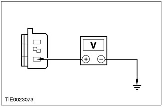
2Measure the voltage between: NOTE:Power Driver Seat - LHD - pin 2 C761 of the electric seat height adjustment motor with electric drive, electrical circuit 33-AH10 (yellow/black), on the wiring side, and "ground" NOTE:Power Driver Seat - RHD - Vehicles built before 12/1999. - pin 2 C760 of the electric seat height adjustment motor with electric drive, electrical circuit 33-AH18 (yellow/black), on the wiring side, and "ground". NOTE:Power Driver's Seat - RHD - Vehicles built from 01/2000. - pin 2 C761 of the electric seat height adjustment motor with electric drive, electrical circuit 33-AH10 (yellow/black), on the wiring side, and "ground" |
|
• Is the voltage more than 10V? |
|
|
→ Yes |
|
|
INSTALL a new power seat height adjustment motor. CHECK the system for proper operation. |
|
|
→ No |
|
|
REPAIR circuit 33-AH10 (yellow/black) or circuit 33-AH18 (yellow/black). CHECK for proper system operation. |
|
PINPOINT TEST B: SEAT HEATING DOES NOT WORK
|
STATES |
DETAILS/RESULTS/ACTIONS |
|
B1: CHECK SWITCHING VOLTAGE SUPPLIED TO SEAT HEATING SWITCH |
|
|
1Enter the ON position. |
|
|
2Press the seat heating switch. |
|
|
• Is the seat heating switch LED on? |
|
|
→ Yes |
|
|
Go to B2. |
|
|
→ No |
|
|
Go to B6. |
|
|
B2: CHECK SWITCHING VOLTAGE SUPPLIED TO THE HEATER MATS OF THE INOPERATING HEATED SEAT |
|
|
1Enter the OFF position. |
|
|
2Disconnect the non-functioning heated seat. |
|
|
3Enter the ON position. |
|
|
4Press the seat heating switch. |
|
|
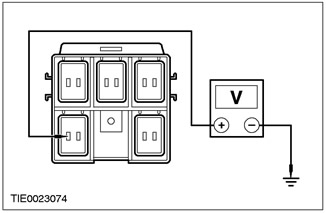
5Measure the voltage between: NOTE:Power Driver's Seat - LHD. - Measure the voltage between pin 1 C30 of heated seat cushion, circuit 15S-HC8 (green/red), harness side and ground. NOTE:Power passenger seat - LHD. - Measure the voltage between pin 1 C31 of heated seat cushion, circuit 15S-HC111 (Green/White), harness side and ground. NOTE:Power Driver's Seat - RHD. - Measure the voltage between pin 1 C31 of heated seat cushion, circuit 15S-HC11 (Green/White), harness side and ground. NOTE:Power passenger seat - RHD. - Measure the voltage between pin 1 C30 of heated seat cushion, circuit 15S-HC8 (green/red), harness side and ground. |
|
• Is the voltage more than 10V? |
|
|
→ Yes |
|
|
Go to B3. |
|
|
→ No |
|
|
REPAIR circuit 15S-HC8 (green/red) or circuit 15S-HC11 (green/white). CHECK system operation for proper operation. |
|
|
B3: CHECK SEAT CUSHION HEATER MAT GROUND CIRCUIT FOR OPEN |
|
|
1Enter the OFF position. |
|
|
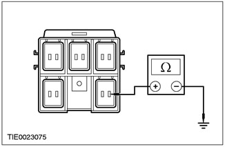
2Measure the resistance between: NOTE:Power Driver's Seat - LHD. - measure the resistance between pin 4 C30 of the non-working heated seat back, circuit 31-HC8 (black), wiring side, and ground. NOTE:Power passenger seat - LHD. - measure the resistance between pin 4 C31 of the inoperative heated seat back, circuit 31-HC11 (black), wiring side, and ground. NOTE:Power Driver's Seat - RHD. - measure the resistance between pin 4 C31 of the inoperative heated seat back, circuit 31-HC11 (black), wiring side, and ground. NOTE:Power passenger seat - RHD. - measure the resistance between pin 4 C30 of the non-working heated seat back, circuit 31-HC8 (black), wiring side, and ground. |
|
• Is the resistance less than 5 ohms? |
|
|
→ Yes |
|
|
Go to B4. |
|
|
→ No |
|
|
REPAIR circuit 31-HC8 (black) or circuit 31-HC11 (black). CHECK for proper system operation. |
|
|
B4: CHECK SEAT CUSHION HEATER MAT CIRCUIT FOR OPEN |
|
|
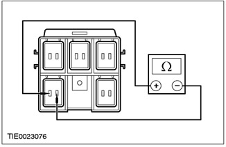
1Measure the resistance of the heating elements: NOTE:Power Driver's Seat - LHD. - measure the voltage between pin 1 C30 of the non-operating heated seat cushion, circuit 15S-HC8 (green/red), element side, and pin 2 C30 of the non-operating heated seat cushion, circuit 15S-HC7 (green/blue), element side. NOTE:Power passenger seat - LHD. - measure the voltage between pin 1 C31 of the non-operating heated seat cushion, circuit 15S-HC11 (green/white), element side, and pin 2 C31 of the non-operating heated seat cushion, circuit 15S-HC10 (green/orange), element side. NOTE:Power Driver's Seat - RHD. - measure the voltage between pin 1 C31 of the non-operating heated seat cushion, circuit 15S-HC11 (green/white), element side, and pin 2 C31 of the non-operating heated seat cushion, circuit 15S-H11 (green/orange), element side. NOTE:Power passenger seat - RHD. - measure the voltage between pin 1 30 of the non-operating heated seat cushion, circuit 15S-HC8 (green/red), element side, and pin 2 C30 of the non-operating heated seat cushion, circuit 15S-HC7 (green/blue), element side. |
|
• Is the resistance 9 ohms (resistance of one heating mat)? |
|
|
→ Yes |
|
|
Go to B5. |
|
|
→ No |
|
|
INSTALL a new heater mat. CHECK the system for proper operation. |
|
|
B5: CHECK SEAT BACK HEATER MAT CIRCUIT FOR OPEN |
|
|
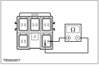
1Measure the resistance of the heater elements between: NOTE:Power Driver's Seat - LHD. - Measure the voltage between pin 3 C30 of the non-operating heated seat back, circuit 15S-HC7 (Green/Blue), element side and pin 4 C30 of the non-operating heated seat back, circuit 31-HC8 (Black), element side. NOTE:Power passenger seat - LHD. - Measure the voltage between pin 3 C31 of the non-operating heated seat back, circuit 15S-HC10 (Green/Orange), element side and pin 4 C31 of the non-operating heated seat back, circuit 31-HC11 (Black), element side. NOTE:Power Driver's Seat - RHD. - Measure the voltage between pin 3 C31 of the non-operating heated seat back, circuit 15S-HC10 (Green/Orange), element side and pin 4 C31 of the non-operating heated seat back, circuit 31-HC11 (Black), element side. NOTE:Power passenger seat - RHD. - Measure the voltage between pin 3 C30 of the non-operating heated seat back, circuit 15S-HC7 (Green/Blue), element side and pin 4 C30 of the non-operating heated seat back, circuit 31-HC8 (Black), element side. |
|
• Is the resistance 9 ohms (resistance of one heating mat)? |
|
|
→ Yes |
|
|
REPAIR circuit 15S-HC7 (green/blue) or circuit 15S-HC10 (green/orange). CHECK system operation for proper operation. |
|
|
→ No |
|
|
INSTALL a new heater mat. CHECK the system for proper operation. |
|
|
B6: CHECK IGNITION VOLTAGE SUPPLIED TO SEAT HEATING SWITCH |
|
|
1Enter the OFF position. |
|
|
2Disconnect the Inoperative Seat Heater Switch. |
|
|
3Enter the ON position. |
|
|
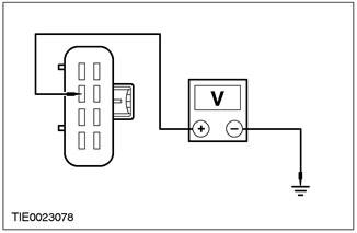
4Measure the voltage between: NOTE:Power Driver Seat - LHD - measure the voltage between pin 2 C694 of the inoperative seat heater switch, circuit 15-HC6 (green/yellow), harness side, and ground. NOTE:Power Passenger Seat - LHD - measure the voltage between pin 2 C695 of the inoperative seat heater switch, circuit 15-HC9 (green/black), harness side, and ground. NOTE:Power Driver's Seat - RHD. - measure the voltage between pin 2 C695 of the inoperative seat heater switch, circuit 15-HC9 (green/black), harness side, and ground. NOTE:Power Passenger Seat - RHD - measure the voltage between pin 2 C694 of the inoperative seat heater switch, circuit 15-HC6 (green/yellow), harness side, and ground. |
|
• Is the voltage more than 10V? |
|
|
→ Yes |
|
|
Go to B7. |
|
|
→ No |
|
|
REPAIR circuit 15-HC6 (green/yellow) or circuit 15-HC9 (green/black). CHECK for proper system operation. |
|
|
B7: CHECK SEAT HEATING SWITCH GROUND CIRCUIT FOR OPEN |
|
|
1Enter the OFF position. |
|
|
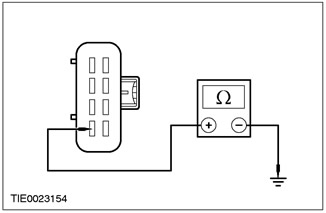
2Measure the resistance between: NOTE:Power Driver Seat - LHD - measure the resistance between pin 4 C694 of the inoperative seat heating switch, circuit 31-LH29 (black), harness side, and ground. NOTE:Power Passenger Seat - LHD - Measure the resistance between pin 4 C695 of the inoperative seat heater switch, circuit 31-LH43 (Black), harness side and ground. NOTE:Power Driver's Seat - RHD. - measure the resistance between pin 4 C695 of the inoperative seat heating switch, circuit 31-LH43 (black), harness side, and ground. NOTE:Power Passenger Seat - RHD - Measure the resistance between pin 4 C694 of the inoperative seat heater switch, circuit 31-LH29 (Black), harness side and ground. |
|
• Is the resistance less than 5 ohms? |
|
|
→ Yes |
|
|
CHECK the validity of the customer's complaint. |
|
|
→ No |
|
|
REPAIR circuit 31-LH29 (black) or circuit 31-LH43 (black). CHECK for proper system operation. |
|
(For more information, please visit the website: fordbook)