
Fig. 6.4. Schematic diagram of the five-speed manual gearbox mod. iB5: 1 – rear cover of the gearbox housing; 2 – gearbox housing; 3 – breather; 4 – clutch release hydraulic drive slave cylinder; 5 – clutch housing; 6 – clutch release bearing; 7 – primary shaft; 8 – secondary shaft; 9 – main gear and differential.
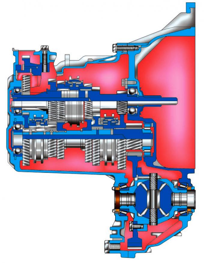
Fig. 6.5. Schematic diagram of the six-speed manual gearbox mod. MTX-75: 1 – reverse gear pinion; 2 – V gear; 3 – leading gear of the 4th gear; 4 – clutch for engaging III and IV gears; 5 – gearbox housing; 6 – leading gear of the 3rd gear; 7 – 2nd gear pinion; 8 – 1st gear pinion; 9 – clutch housing; 10 – primary shaft; 11 – differential housing; 12 – main gear drive pinion; 13 – 1st gear drive pinion; 14 – clutch for engaging 1st and 2nd gears; 15 – leading gear of the 2nd gear; 16 – third gear pinion; 17 – secondary shaft; 18 – 4th gear pinion; 19 – leading gear of the 5th gear; 20 – clutch for engaging 5th gear and reverse gear; 21 – Reverse gear drive pinion.
The mechanical gearbox mod. iB5 (Fig. 6.4) or MTX-75 (Fig. 6.5) is made according to a two-shaft scheme with five synchronized forward gears. The mechanical gearbox mod. MMT6 is made according to a three-shaft scheme with six synchronized forward gears.
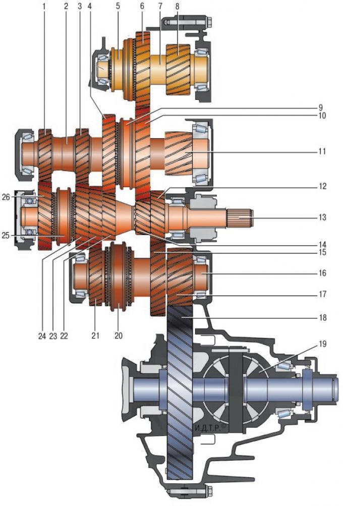
Fig. 6.6. Schematic diagram of the six-speed manual gearbox mod. MT-66: 1 – gear 6; 2 – secondary shaft of I and II gears; 3 – V gear; 4 – leading gear of the 2nd gear; 5 – reverse gear engagement clutch; 6 – Reverse gear drive pinion; 7 – secondary shaft of reverse gear; 8 – reverse gear output gear; 9 – clutch for engaging 1st and 2nd gears; 10 – leading gear of 1st gear; 11 – output gear of I and II gears; 12 – third gear pinion; 13 – primary shaft; 14 – 1st gear pinion; 15 – leading gear of the 3rd gear; 16 – secondary shaft of III and IV gears; 17 – output gear of III and IV gears; 18 – driven gear of the main pair; 19 – differential housing; 20 – clutch for engaging III and IV gears; 21 – leading gear of the 4th gear; 22 – 2nd gear pinion; 23 – 4th gear pinion; 24 – leading gear of the 5th gear; 25 – clutch for engaging IV and VI gears; 26 – leading gear of the 6th gear.
The mechanical gearbox mod. MT-66 (Fig. 6.6) is made according to the four-shaft scheme with triple synchronization of the first and second gears, with double synchronization of the third gear and with single synchronization of the fourth, fifth and sixth gears. The gearbox and the main gear with the differential have a common housing. The clutch housing is attached to the front part of the gearbox housing. A stamped steel cover is installed on the rear part of the gearbox housing.
Forward gears are engaged by axial movement of synchronizer clutches mounted on shafts. The gear shift mechanism is located inside the gearbox housing on its left side. There are two mechanism levers outside - the gear selection lever and the shift lever.
The manual transmission control drive consists of a gear shift lever linkage with a ball joint mounted on the body base, two gear shift and selection cables, and a mechanism installed in the gearbox housing. To ensure precise gear engagement, the gear shift lever of the shift mechanism is made in one piece with a massive counterweight.
The gear selection and shift cables are structurally different from each other and are not interchangeable.
The main transmission is made in the form of a pair of cylindrical gears, selected for noise. Torque is transmitted from the driven gear of the main transmission to the differential and then to the front wheel drives.
The differential is conical, with two satellites. The tightness of the connection of the internal joints of the front wheel drives with the differential gears is ensured by seals.
The automatic transmission with adaptive control system provides the choice of the optimal gear shift mode for almost any driving style and road conditions. The automatic transmissions installed with the 2.3-liter gasoline engine and the 2-liter diesel engine are identical in design and differ only in gear ratios.
A special feature of automatic transmissions of Ford Mondeo cars compared to automatic transmissions of previous generations is the ability to switch from a fully automatic control mode to a manual mode (the so-called sequential gearbox), in which the driver independently selects the moment of switching to an upshift during acceleration of the car. This allows, if desired, to achieve more intense acceleration compared to the automatic mode, artificially delaying the switching to an upshift, and to bring the engine crankshaft speed to the range of maximum torque. At the same time, the electronic control system constantly monitors the speed of the car and the engine load, eliminates driver errors, not allowing him to engage a higher gear at low speed to avoid engine overload, or a lower gear at too high a speed, which eliminates the possibility of exceeding the maximum permissible engine crankshaft speed. When the car speed decreases, the gears are automatically switched to lower ones without driver intervention. When the car comes to a complete stop, the first gear is automatically engaged.
The automatic transmission consists of a torque converter, pump, planetary gear, multi-plate clutches, multi-plate brakes and a valve block.
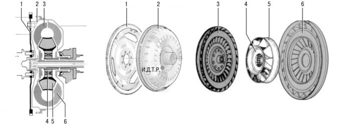
Fig. 6.7. Torque converter: 1 – drive disk; 2 – hydraulic transformer housing; 3 – turbine; 4 – overrunning clutch; 5 – reactor; 6 – pump wheel.
The torque converter (Fig. 6.7) acts as a clutch and serves to smoothly connect the engine and gearbox mechanism, increasing torque at the start of the vehicle's movement. The torque converter housing is connected to the engine crankshaft via a drive disk and rotates constantly when the engine is running.
The internal cavity of the torque converter is filled with working fluid for automatic transmissions. The engine crankshaft rotates the torque converter and drives the pump wheel, which creates working fluid flows in the direction of the turbine wheel. The turbine wheel begins to rotate due to the working fluid flows created by the pump wheel.
With a large difference in the rotation speed of the turbine and pump wheels, the reactor changes the direction of the liquid flow, increasing the torque. As the frequency difference decreases, it is excluded from operation, since it is installed on an overrunning clutch.
The pump, mounted in the front part of the gearbox housing, creates pressure and supplies working fluid to all systems in the gearbox.
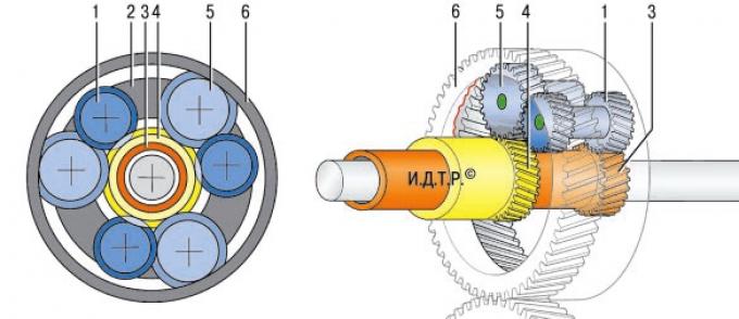
Fig. 6.8. Planetary gearbox of the Ravigne system: 1 – long satellite; 2 – driver; 3 – small sun gear; 4 – large sun gear; 5 - short satellite; 6 – crown gear.
The Ravigne system planetary gearbox (Fig. 6.8) is a gear transmission with external and internal gear engagements, which provides various methods of connecting its elements to obtain different gear ratios.
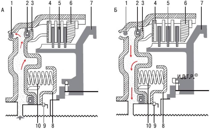
Fig. 6.9. Multi-plate clutch operation diagram: A – multi-plate clutch is engaged; B – multi-plate clutch disengaged; 1 – ball valve; 2 – sealing ring; 3 – piston; 4 – friction disc; 5 – friction disc with linings; 6 – thrust disc; 7 – clutch hub; 8 – spring stop; 9 – retaining ring; 10 – return spring.
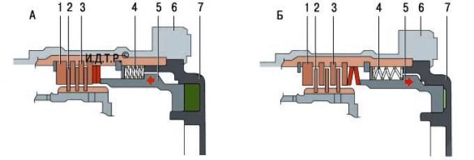
Fig. 6.10. Disc brake operation diagram: A – brakes on; B – brakes off; 1 – thrust disc; 2 – friction brake discs with linings; 3 – friction disc; 4 – return spring; 5 – piston; 6 – gearbox housing; 7 – gearbox housing cover.
The operating principles of a multi-plate clutch (Fig. 6.9) and a disc brake (Fig. 6.10) are very similar. The difference is that a multi-plate clutch connects the gearbox links to each other, while a disc brake connects to the gearbox housing. The working fluid supplied to the clutch activates the piston, causing the friction discs to compress. The links locked by the clutch begin to rotate as a single unit.
When the disc brakes are disengaged, the working fluid stops being supplied to the clutch and the piston, under the action of the return spring, returns to its original position.
The design feature of the multi-plate clutch is that it is in constant rotation. Under the action of centrifugal force acting on the working fluid, pressure is created that does not allow the clutch to unlock. Additionally, a ball valve is installed in the clutch, located as close as possible to the edge of the center of the clutch. When the pressure of the working fluid in the chamber of the multi-plate clutch increases, the ball valve closes the drain hole, and when the pressure in the chamber decreases, the ball valve, under the action of centrifugal force, opens the drain hole and the clutch is unlocked.
The automatic transmission control drive is cable-operated and is constructed on the same principle as the manual transmission control drive, but differs from it in the number and design of parts. The automatic transmission selector is installed in the same place on the floor tunnel as the manual transmission control lever and is connected to the control unit on the transmission by a cable.
The design of the differential of an automatic transmission is completely similar to that of a manual transmission.
Repairing a gearbox, especially an automatic gearbox, requires a large set of special tools and appropriate training of the performer, so this section only covers removing and installing the gearbox, replacing its seals, and repairing the drive. If necessary, repair the gearbox at a specialized service center.
(The original source of this article can be found at FORDBOOK.ru)