Any discrepancy between the actual values measured on the vehicle and the reference values specified below is due to wear and deformation of suspension parts or deformation of the body.
WARNING: Replacing or repairing suspension components may cause changes in wheel alignment, so checking wheel alignment is essential.
The wheel alignment angles of the equipped vehicle (with a sedan body and standard suspension) are given in Table 7.1.
After installing the car on the stand (immediately before checking the angles), "squeeze" the car's suspension, applying a force of 392-490 N (40-50 kgf) two or three times, directed from top to bottom, first to the rear bumper, and then to the front. The car's wheels should be parallel to the longitudinal axis of the car.
When checking and adjusting the front wheel alignment angles, first check the caster angle, then the camber angle, and lastly the toe-in.
The longitudinal tilt angle of the front wheel pivot axis is formed by the vertical and the line passing through the middle of the upper support of the telescopic strut and the center of the sphere of the ball joint fixed to the lower arm. The design of the vehicle does not provide for adjustment of the longitudinal tilt angle of the pivot axis. If the angle deviates from the nominal value, replace damaged and deformed parts.
The front wheel camber angle is characterized by the deviation of the average plane of rotation of the wheel from the vertical. The car design does not provide for adjustment of the front wheel camber angle.
Front wheel toe-in is the angle between the plane of rotation of the wheel and the longitudinal axis of the vehicle. Front wheel toe-in is adjusted by changing the length of the steering rods.
Check the following rear wheel alignment angles.
The rear wheel camber angle is characterized by the deviation of the average plane of rotation of the rear wheel from the vertical. The rear wheel camber angle adjustment is not provided by the vehicle design.
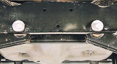
Rear wheel toe is the angle between the plane of rotation of the rear wheel and the longitudinal axis of the vehicle.
The toe-in angle of the rear wheels is adjusted by turning the adjusting bolts that secure the rear lower arm to the rear suspension subframe.
Table 7.1
WHEEL ALIGNMENT ANGLES
| Parameter | Nominal value | Acceptable value | Maximum difference in the installation angles of the right and left wheels |
| front wheels | |||
| Longitudinal tilt of the steering axis (caster) | 2°56' | From 3°58' up to 1°55' | 1°00' |
| Collapse | –0°35' | From 0°41'? to -1°51' | 1°15' |
| Convergence | 0°12?' ±0°08' | 0°12?' ±0°21' | - |
| rear wheels | |||
| Collapse | –1°19' | From -0°04' up to -2°34' | 1°15' |
| Convergence | 0°24'±0°08' | 0°24'±0°21' | - |