Note: Before removal, mark the position of the subframe for correct subsequent installation.
Warning: When removing and installing, the gearbox must rest securely on a jack.
It is better to do this work with an assistant.
When removing the gearbox, the entire subframe and wheel drive shafts are removed.
In addition, you will need a device to lift the engine.
To remove the gearbox on a 16-valve engine:
- Disconnect the negative battery terminal and all other wires connected to it. Cable ties should be cut and replaced with new ones when installing;
- remove the battery;
- loosen the nuts in the center of both chassis shock absorber struts (on both sides) by five turns;
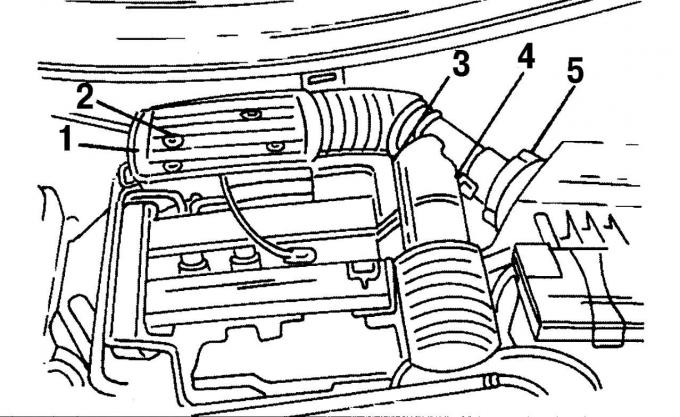
Fig. 22. Fastening of air intake pipes: 1 — fastening bolts, 2 — plug, 3 — plug block, 4 — clamp, 5 — low-pressure hose
- unscrew the four screws 1 (see Fig. 22) securing the air duct;
- remove plug 2 from the air flow meter and remove clamps 3 of the hose on the same side;
- remove the multi-pin plug 4 of the intake air sensor;
- remove low pressure hose 5;
- remove the air intake pipe;
- disconnect the ventilation hose between the air filter and the cylinder head cover;
- remove the rubber ring;
- lift and remove the air filter from its mount;
- From the engine compartment, disconnect the electrical wires from the gearbox. This includes the multi-pin plug for the reversing light switch and the ground ribbon cable between the gearbox housing and the body (both near the air filter support);
- disconnect the wiring from the clutch slave cylinder. To do this, remove the spring clamp and pull the wire straight out of the connection. Clamp the wiring from the gearbox and tie it with a wire in a suitable place;
- remove the screws between the engine and gearbox at the top;
- unscrew the upper starter mounting screw and remove the connected ground cable;
- disconnect all wire ends and low pressure hoses;
- disconnect the fuel lines;
- Loosen the wheel nuts and the wheel hub nut on the right side and place the front of the vehicle on supports;
- lift the power unit;
- remove both front wheels;
- unscrew the shield in the wheel well on the side of the engine belt pulley;
- unscrew the mudguard on the bottom of the car;
- put the car on supports;
- disconnect the shock absorber bracket and the hydraulic steering lines from the subframe;
- disconnect the anti-roll bar linkage and control arms from the chassis shock absorber strut;
- disconnect the steering linkage joint from the steering knuckle;
- disconnect the ball joint on the left and right from the lower surface of the steering knuckle;
- remove the multi-pin plug from the lambda probe and disconnect the cable clamp;
- Disconnect the low pressure hose from the Air-Pulse system filter;
- unscrew the steering drive pipeline bracket;
- remove the exhaust system completely;
- unscrew the gearbox drive cable from the gearbox and remove it together with the bracket;
- unscrew the steering control and the right stop from turning the engine from the subframe;
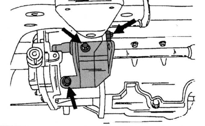
Fig. 156. Location of the mounting points of the stop console
- unscrew the three fastening elements (Fig. 156) and release the rear stop console from the drive;
- unscrew the middle screw from the left stop from turning the engine and remove the stop;
- unscrew the Air-Pulse system filter from the mount on the stop;
- unscrew the radiator bracket;
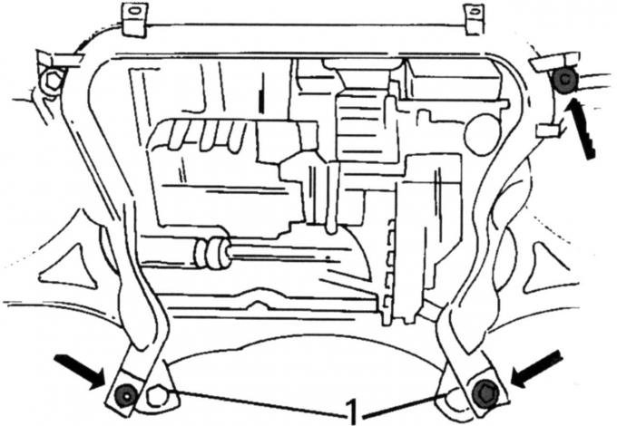
Fig. 37. Location of screws (indicated by arrows) of the subframe: 1 - guide pins
- unscrew the four subframe mounting screws and lower the subframe (see Fig. 37);
- drain the oil from the gearbox;
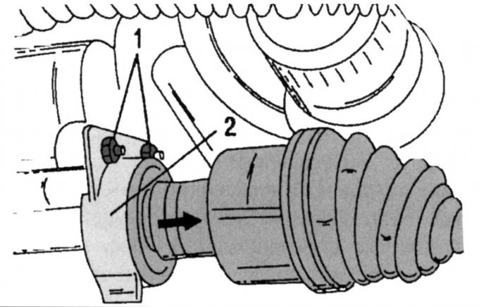
Fig. 157. Removing the right wheel drive shaft (the arrow indicates the direction of removal): 1 — thrust bearing screws; 2 - heat shield
- remove the right wheel drive shaft. After unscrewing screws 1 (see Fig. 157) and unscrewing heat shield 2, you can remove the shaft from the gearbox (see below). Tie the shaft to the suspension with a wire, without creating a large angle in the constant velocity joint;
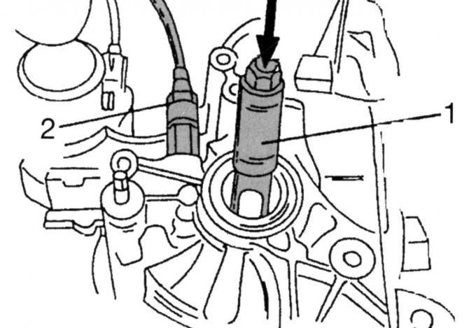
Fig. 158. Removing the left wheel drive shaft: 1 — mandrel; 2 - Speedometer spiral mounting nut
- a special mandrel is used to remove the left drive shaft (Fig. 158). Use it to knock the shaft out of its seat and remove it from the gearbox. Tie the shaft to the suspension with a wire, without creating a large angle in the constant velocity joint. Unscrew nut 2 of the speedometer spiral with an oblique mesh knurling and remove the spiral. There is also a speed sensor nearby, which must be disconnected;
- place a car jack (with a wooden spacer between the jack head and the engine/drive) under the engine/drive and lift the power unit to relieve the engine mount;
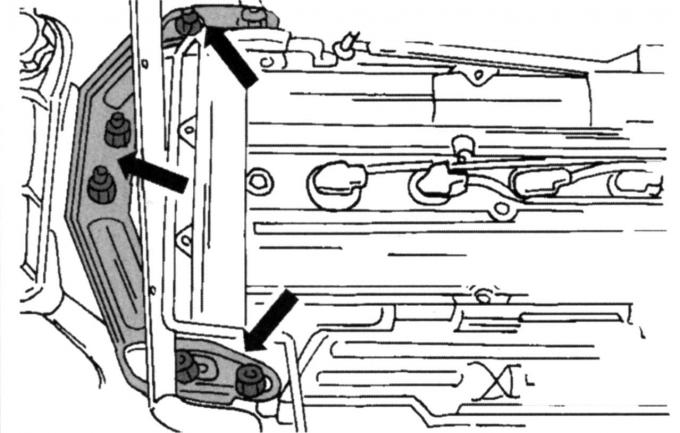
Fig. 32. Right engine mount mounting locations
- unscrew the fastening element of the right engine mount. Fig. 32 shows how the suspension bracket is secured;
- unscrew the five self-locking nuts (replace them with new ones when installing);
- remove the bracket;
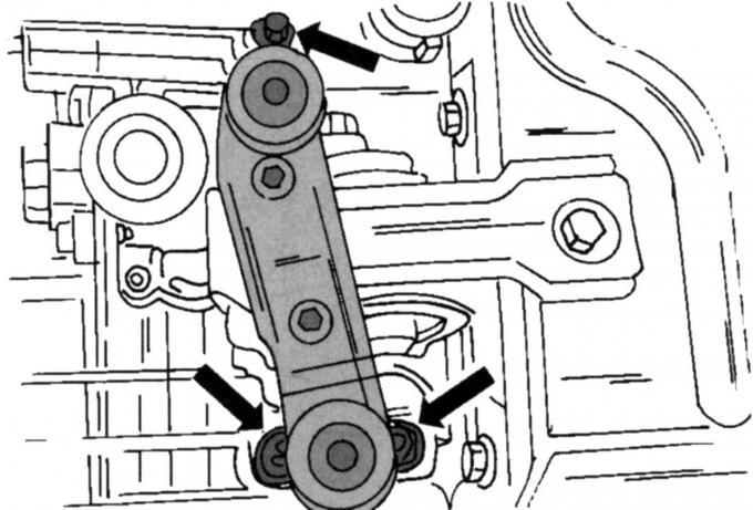
Fig. 33. Left suspension mounting locations on the drive
- on the opposite side, unscrew the self-locking nuts of the rear engine mount from the gearbox (see Fig. 33);
- lower the gearbox so that it is at the same height as the left longitudinal beam;
- unscrew the remaining screws securing the gearbox to the engine and the remaining screws securing the starter;
- lift the car;
- disconnect the brake booster low pressure hose at the intake manifold;
- check if the gearbox is securely held on the car jack and carefully remove it. Make sure that nothing is connected.
Note: All self-locking nuts, cut cable ties and other fasteners must be replaced with new ones. When installing the engine, the drive unit must be aligned with the subframe.
Installation is carried out in reverse order, taking into account the following:
- with an assistant, jack up the gearbox and attach it to the engine flanges. The clutch release bearing should be pressed firmly towards the inner side;
- screw in the engine mounting screws to the gearbox and carefully tighten to a torque of 40 Nm;
- tighten the lower starter mounting screws to 48 Nm;
- lower the car;
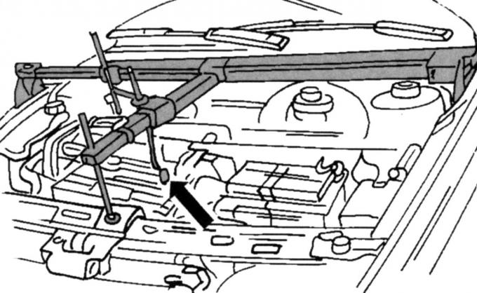
Fig. 34. Device for lifting the engine and drive when hanging the engine
- install a lifting mechanism to lift the engine (see Fig. 34);
- screw the fastening elements of the left engine mount (see Fig. 33) onto the gearbox without tightening them;
- screw the fastening elements of the right engine mount (see Fig. 32) onto the gearbox without tightening them;
- install the left drive shaft;
- install a new snap ring into the groove of the shaft before pushing the end of the shaft into the gearbox;
- slide the right drive shaft into the gearbox, install the thrust bearing and tighten both screws 1 (see Fig. 157) to a torque of 27 Nm;
- install heat shield 2;
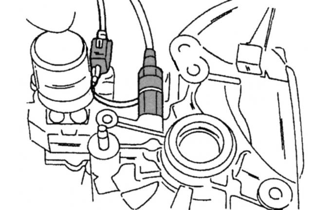
Fig. 159. Location of speedometer elements: 1 — sensor; 2 - spiral
- screw in the speed sensor and the speedometer spiral (Fig. 159);
- install the subframe;
- install the front suspension;
- tighten the ground terminal between the gearbox and the body to a torque of 47 Nm;
- install the exhaust system parts on the rubber rings and tighten the connection to the exhaust manifold with a torque of 40 Nm;
- install the wheels;
- lower the car;
- tighten the wheel nuts.
To remove the transmission from a vehicle equipped with a V6 engine, you must do the following:
- disconnect the battery and remove it;
- set the gearshift lever to neutral position;
- remove the rubber cover upwards;
- disconnect both ventilation hoses from the air intake hose side;
- Loosen the hose clamp on the throttle body;
- disconnect the low pressure hose on the back side;
- remove the air flow meter plug from the front;
- release the air filter from the rubber suspension and remove it;
- drain the brake fluid from the reservoir;
- loosen the nuts in the center of both chassis shock absorber struts on both sides by five turns;
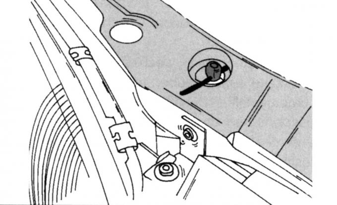
Fig. 161. Radiator fastening
- secure the radiator (Fig. 161);
- release the water pump hose from the spring clamp;
- unscrew the three screws and remove the cover;
- remove the water pump casing;
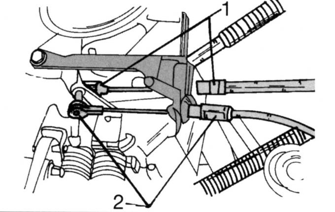
Fig. 162. Fastening the cables: 1 — speed control rod cable; 2 - throttle control cable
- unhook the traction rods on the cables (Fig. 162);
- unscrew the ground cable fastening and move the cable to the side;
- remove the two wire plugs on the gearbox. Pull one off and disconnect the other (speed sensor and reverse indicator lights);
- unscrew both upper screws securing the gearbox to the engine;
- lift the power unit (see Fig. 34);
- disconnect the clutch hydraulic drive;
- collect the fluid flowing out of the hydraulic drive;
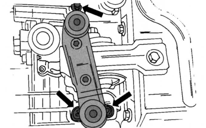
Fig. 163. Mounting locations of the left engine mount on the gearbox
- disconnect the left gearbox mount from the gearbox (Fig. 163);
- place the front of the car on supports and drain the transmission oil;
- clean the plug and tighten it (45 Nm);
- disconnect the catalytic converter from the flange connections at the front and rear and remove it;
- from the inside, unscrew and remove the trim of both wheel arches;
- disconnect the anti-roll bar linkage and control arms from the chassis shock absorber strut;
- disconnect the ball joint on the left and right from the lower surface of the steering knuckle;
- remove the cover under the radiator;
- unscrew the shock absorber support from the subframe;
- disconnect the oil line clamp on the subframe;
- unscrew the screws on the bottom side;
- unscrew the middle screw;
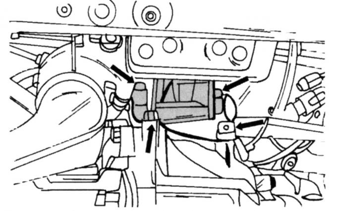
Fig. 164. Fastening the left engine support (V6 engine)
- unscrew the supporting console of the stop (Fig. 164);
- unscrew the middle screw on the right stop from turning;
- unscrew the three screws and remove the stop;
- unscrew the supporting console (see Fig. 156);
- unscrew the subframe screws (see Fig. 37) and lower it at the rear;
- remove the steering heat shield;
- unscrew the shift cable and the selector cable from the gearbox and remove them together with the bracket;
- unscrew the steering from the subframe (two screws on each side);
- place a car jack under the subframe (see Fig. 37) and completely unscrew the subframe mounting screws;
- lower the subframe;
- remove the right wheel drive shaft. Secure the shaft with a wire to the suspension, without creating a large angle in the constant velocity joint;
- remove the drive shaft on the left using a special mandrel (see Fig. 158). Secure the shaft to the suspension without creating a large angle in the constant velocity joint;
- unscrew nut 2 with oblique mesh knurling and remove the speedometer spiral;
- place a car jack under the engine/drive (with a wooden spacer between the jack head and the engine/drive) and lift the power unit;
- unscrew the lower screws securing the gearbox to the engine: three on the rear side, three on the front side;
- remove the starter;
- remove other components installed on the gearbox;
- lower the gearbox so that it can be removed.
Installation is carried out in reverse order, taking into account the following:
- align the drive unit with the subframe;
- install the gearbox on a car jack and align the engine flanges;
- screw in the gearbox mounting screws to the engine and tighten them to a torque of 40 Nm;
- install the starter and tighten the screws to 25 Nm;
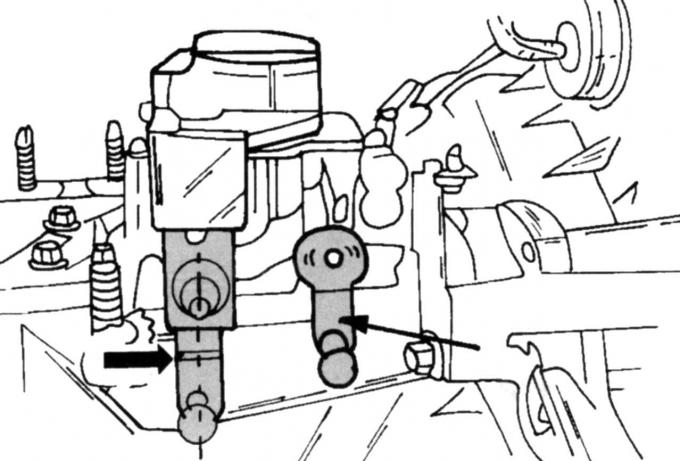
Fig. 165. Position of gearbox levers
- set the gearbox to "neutral". Both levers (Fig. 165) must be in the position shown in the figure;
- install the shift cable mounting bracket, tighten the nuts and attach both shift cables;
- connect the shift cables to the levers and put on the clip clamps;
- set the steering to the correct position, insert the screws and tighten the screw on the left and right to a torque of 130 Nm;
- install the heat shield and oil line clamp;
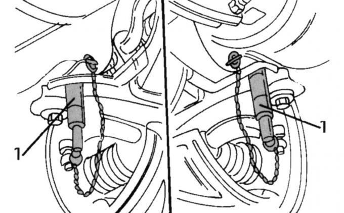
Fig. 166. Location of guide pins (15-097)
- install the subframe. Insert both guide pins (Fig. 166) and align the subframe so that the guide pins are in the middle of the holes in the body;
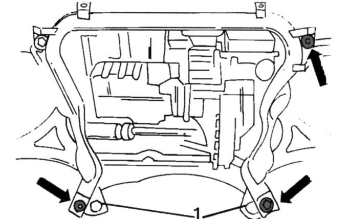
Fig. 167. Location of guide pins
- install the steering as shown in Fig. 167;
- tighten the screws shown by the arrows to a torque of 130 Nm;
- remove both guide pins 1;
- install a lifting device;
- secure the ropes in the lifting eyes;
- install the right stop bracket against rotation;
- tighten the screws to a torque of 85 Nm;
- set the stop;
- tighten the three screws to a torque of 48 Nm;
- tighten the middle screw to 120 Nm (after installing the left torque stop);
- install the subframe;
- tighten the subframe mounting screws to a torque of 130 Nm;
- install the left stop console against rotation;
- tighten the screws to a torque of 48 Nm;
- insert the middle screw and tighten it to 30 Nm;
- install the catalytic converter with a new seal and tighten the screws in the flange connection to a torque of 40 Nm;
- install a protective cover under the radiator;
- Install the left drive shaft into the gearbox. Install a new snap ring into the shaft groove before installing the end of the shaft into the gearbox;
- install the right drive shaft into the gearbox;
- screw on the thrust bearing and tighten both screws 1 (see Fig. 157) to a torque of 27 Nm;
- connect the speed sensor and the speedometer spiral (see Fig. 159);
- install the front suspension;
- tighten the upper gearbox-to-engine mounting screws to 40 Nm;
- carry out further installation in the reverse order of removal;
- remove air from the hydraulic drive of the brake system.