Contents: The most important letter… ↳ Model year 1991 ↳ Explanation of the diagram ↳ Wire color decoding ↳
If you need to detect a fault in the electrical system or install additional electrical components, you cannot do without an electrical diagram. Using the diagram, you can detect the presence of electric current and wire connectors. The corresponding electrical circuit must be closed, otherwise there will be no electric current in it. It is not enough, for example, to apply voltage to the positive (+) terminal of the headlight without simultaneously closing the electrical circuit through the ground (-).
Therefore, the battery ground (-) wire is also connected to the car body. However, sometimes this ground connection is not sufficient, and the corresponding consumer is connected to the ground directly by a wire, the insulation of which is usually painted black. A switch, relays, fuses, measuring instruments, electric motors or other electrical components can be connected in a separate electrical circuit. In order to be able to connect these consumers correctly, the individual connecting wires have different colors.
To visually organize the intertwining of wires, at least in the electrical diagram, the entire electrical system of the car is divided into individual electrical circuits. Electrical components that are interconnected are depicted on the overall electrical diagram.
Parts that function in multiple electrical circuits are shown in each electrical circuit.
Note: The images of parts and wires are not to scale. For example, an electrical wire longer than one meter in an electrical diagram may have the same length as a wire that is only a few centimeters long.
The most important letter designations of terminals
Terminal 15 is supplied with current through the ignition switch. Current flows through the wires only when the ignition is on. The wires are usually black or black with colored stripes.
Terminal 30. Battery voltage is always applied to this terminal. The wires are mostly red or red with colored stripes.
Terminal 31 connected to ground. Ground wires are usually brown.
Each electrical diagram has letter designations (A through F) at the left and right edges, and numeric designations (1 through 16) at the top and bottom edges. These designations can be used to help locate a particular part on the diagram if the part's position is previously recorded as a sequence of the corresponding letter and number.
The letters on the conductors in the electrical diagram indicate the colors of the wires in the car. The decoding of the colors of the wires is placed immediately before the first electrical diagram.
The designation of plug and terminal connectors begins with the letter C (for example, C-1108). Designations of soldering points begin with the letter S, and designations of ground connection points begin with the letter G.
The left side of the vehicle, when viewed in the direction of travel, is designated on the electrical diagram by the symbols LH, and the right side by the symbols RH.
Model year 1991
Due to lack of space, it is not possible to consider diagrams for all engine variants and model variants, as well as for each model year. The proposed electrical diagrams apply primarily to models from 1985 to 1992. However, owners of newer car models can also use the proposed diagrams.
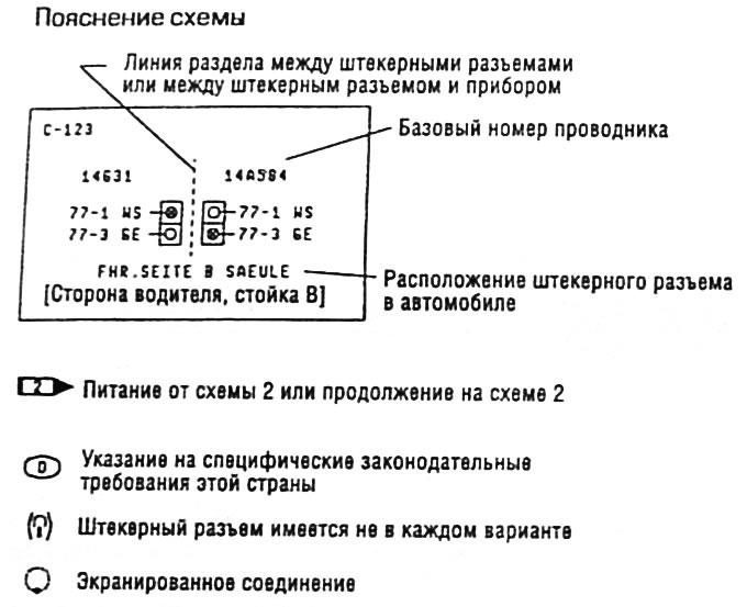
Explanation of the diagram
Wire color decoding
- BL - blue
- BR - brown
- GE - yellow
- GP - grey
- GN - green
- RS - pink
- AT - red
- SW - black
- VI - purple
- WS - white
This article was borrowed from the website (fordbook)