Note: Before removing, mark the position of the subframe for correct subsequent installation.
Warning: The gearbox must be securely jacked up when removing and installing.
An assistant is required for this operation.
When removing the gearbox, the entire subframe is removed, as well as the wheel drive shafts.
When removing, you will need a device to lift the engine.
To remove the gearbox, perform the following operations:
- Disconnect the battery. The cable ties must be cut and replaced accordingly with new ones when installed;
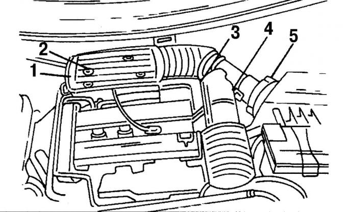
Pic. 22. Fixing the air intake pipes: 1 - mounting bolts, 2 - plug, 3 - plug, 4 - clamp, 5 - low pressure hose
- remove four screws 1 (see fig. 22) fastenings;
- remove plug 2 from the air meter and remove hose clamps 3 on the same side;
- Remove the multi-pin plug 4 of the intake air sensor;
- Remove hose 5 low pressure;
- remove the suction air pipe;
- Disconnect a ventilating hose between the filter and a cover of a head of the block of cylinders;
- unhook the rubber ring on the right, lift and remove the air filter from the mount;
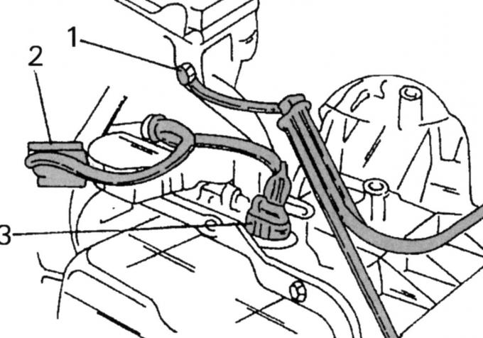
Pic. 168. An arrangement of conducting of a transmission: 1 — a negative wire; 2, 3 - multi-pin plugs
- disconnect the wiring from the gearbox (pic. 168);
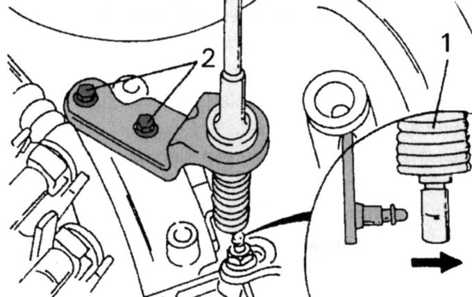
Pic. 169. Attaching the transmission cable: 1 - spring clip; 2 - screws
- disconnect the shift cable (pic. 169). To do this, remove the spring clip 1 from the cable on the automatic transmission control lever and unscrew the screws 2;
- loosen the wheel nuts;
- place the car in front on supports;
- Remove both forward wheels;
- on the side of the engine pulleys, unscrew the fastening elements of the protective cover in the wheel arch;
- install the car on the right and left on supports;
- disconnect the system of rods and levers of the anti-roll bar from the shock absorber strut of the chassis and the joint of the steering link rod from the bipod;
- Disconnect the left and right ball joint from the lower surface of the steering knuckle;
- unscrew the mudguard under the front of the car and drain the coolant from the cooling system;
- remove the multi-pin plug from the lambda probe and disconnect the cable tie;
- Disconnect the low pressure hose from the Air-Pulse system filter;
- Remove details of system of release;
- unscrew the steering and rear stop from turning the engine away from the subframe. The steering screws are hard to get to. The Ford service center uses a specially bent ring wrench for this;
- release fastenings and release the back gauge console from the gearbox;
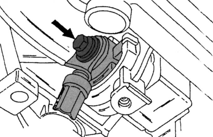
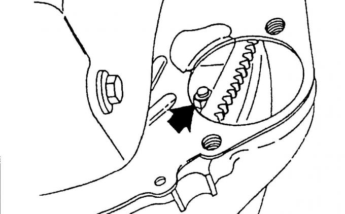
Pic. 170. The location of the screw fastening the front stop
- Turn out the average screw shown on fig. 170, from the front stop of the engine from cranking;
- unscrew the Air-Pulse system filter from the mount on the anti-rotation stop;
- Turn away an arm of fastening of a radiator;
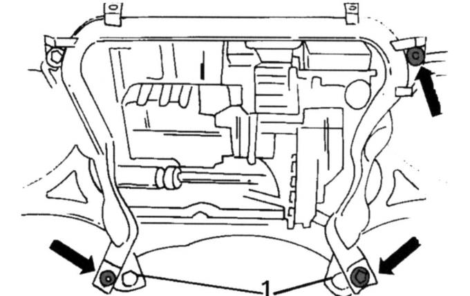
Pic. 167. Location of guide pins
- unscrew the four screws securing the subframe (see fig. 167) and drop it. Before removal, mark the position of the subframe in the mount;
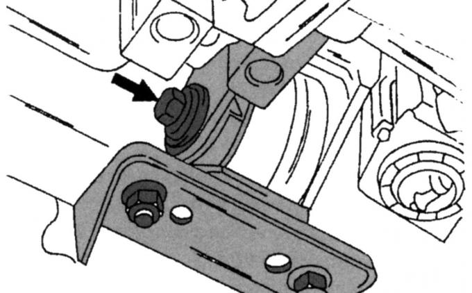
Pic. 171. The location of the rear stop screw
- unscrew the back stop (pic. 171) gearboxes;
- Disconnect the oil line on the rear side between the gearbox and the oil cooler;
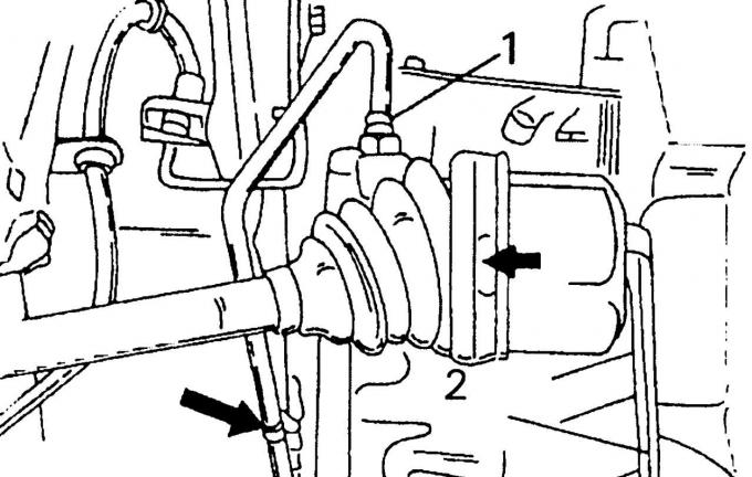
Pic. 172. Removing the left drive shaft: 1 - oil pipeline; 2 - installed lever
- to remove the drive shaft, install the tire mounting lever as shown in fig. 172, behind the CV joint and jerk out the joint;
- fix the shaft so that the hinge cannot bend over;
- Remove the wheel drive shaft;
- fasten the shaft to the chassis without creating a large angle in the constant velocity joint;
- Disconnect the oil line at the front between the gearbox and the oil cooler;
- unscrew the two screws on the underside of the gearbox and remove the cover. In this case, the ring gear and torque converter will become visible. Unscrew the screws one by one, and the crankshaft must be turned until all the screws appear in turn at the bottom of the gearbox;
- disconnect both multi-pin plugs from the thermostat housing, disconnect the hoses and remove the thermostat housing;
- disconnect the oil line in the front between the gearbox and the oil cooler;
- put the car jack under the engine/drive (with wooden spacer between jack head and motor/drive) and raise the power unit;
- Turn away in the top part screws of fastening of a transmission to the engine;
- Turn away the right suspension bracket of the engine;
- take out the bracket;
- on the opposite side, unscrew the self-locking nuts of the left engine mount from the gearbox;
- lower the gearbox so that it is at the same height as the left longitudinal beam, and raise the car again;
- Turn out the remained screws of fastening of a transmission to the engine and the remaining screws of fastening of a starter;
- Check that the gearbox is securely jacked up and carefully remove it from the engine.
When installing, replace all self-locking nuts and cut cable bundles with new ones.
To install the gearbox, do the following:
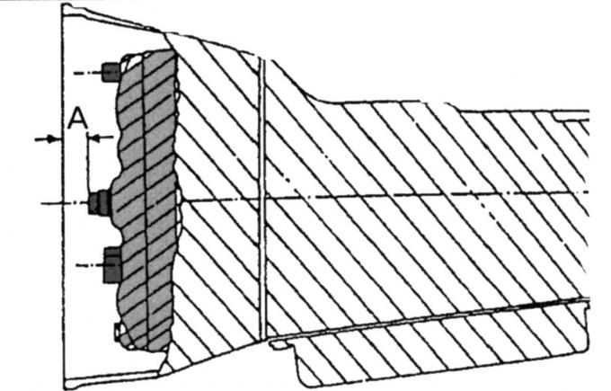
Pic. 173. Place of measurement of distance «A»
- Insert the torque converter into the gearbox. To ensure its normal fit, you need to measure the distance from the mating surface of the gearbox to the torque converter pin. To do this, put a ruler on the surface and take a measurement with a depth gauge (pic. 173). This dimension should be 10 mm. If the size is smaller, then the torque converter is not properly engaged with the oil pump;
- install the gearbox on the jack, ask the assistant to hold it and press it against the engine flange;
Pic. 174. Mounting the drive disk on the torque converter
- at the bottom of the gearbox, turn the crankshaft and the torque converter until the first screw can be inserted (pic. 174). Slightly tighten the screw and turn the crankshaft so that the remaining screws can be screwed in;
- evenly tighten all screws to 36 Nm;
- screw in the screws securing the gearbox to the engine and slowly tighten to 40 Nm;
- tighten the lower starter mounting screws to 48 Nm;
- lower the car on wheels;
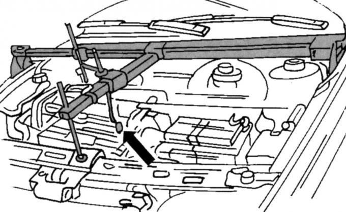
Pic. 34. Device for lifting the engine and drive when hanging the engine
- install the lifting device (see fig. 34);
- screw the left engine mount on the gearbox without tightening the nuts;
- Install the right engine mount. Do not tighten the nuts;
- Establish in a transmission a shaft of a drive of wheels at the left;
- insert a new circlip into the groove of the shaft before pushing the end of the shaft into the gearbox. When installing the shaft, do not damage the O-ring;
- on the rear side, screw the oil line between the gearbox and the oil cooler and tighten to 23 Nm;
- fix the wiring with a clamp;
- fix the wiring on the front side;
- slide the right drive shaft into the gearbox, screw on the thrust bearing and tighten both screws 1 to 27 Nm;
- fix the heat shield 2;
- Establish a back emphasis of the engine;
- tighten the middle screw by hand;
- Install the subframe as described when installing the engine;
- Further assembly is carried out in the reverse order of removal.
Connection tightening torques, Nm:
- screws (see fig. 170 and 171) 120
- fastening to the exhaust manifold 40
- wheel nuts 85
Visitor comments