Warning: See paragraph 2.
Examination
1. Check if battery voltage is being supplied to the center pin of the ignition coil connector (see paragraph 2). Disconnect the negative battery cable (chapter 5A).
2. Disconnect the coil connector if it has not been previously disconnected.
3. Using an ohmmeter, measure the resistance on the primary windings of the coil, connecting the ohmmeter to the coil contacts as follows. First connect it to one of the outer pins and the center pin, and then to the other outer pin and the center pin. Compare the obtained readings with the regulated resistance of the primary circuit (see Technical Requirements).
4. Disconnect the spark plug wires. Note how they are connected, or label them as indicated in chapter 1. Check the resistance with an ohmmeter to make sure that there is no open circuit in the circuit, and the resistance of the secondary winding of the coil corresponds to the regulated one. To do this, connect an ohmmeter to each pair of high voltage wire terminals. On models with 4-cylinder engines, terminals 1 and 4, as well as terminals 2 and 3, are connected to the secondary winding. On models with V-shaped 6-cylinder engines, terminals 1 and 5, 3 and 4, 2 and 6 are connected to the secondary winding. After that, switch the ohmmeter to the maximum resistance measurement mode. Make sure there is no short between pairs of terminals. That is, the resistance between terminals 1 and 2 or 4 and 3, as well as between any terminal and ground, must be infinite.
5. If any of the ohmmeter readings does not match the description in step 4, replace the coil. The following verification procedures should be performed by dealers.
Removal and installation
Models with 4-cylinder engines
Note: On models with 4-cylinder engines, the ignition coil is mounted on a bracket located behind the cylinder head.
6. Disconnect the negative battery cable (chapter 5A).
7. Remove the air mass meter and resonator (chapter 4).
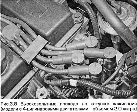
8. Disconnect the electrical connectors on each side of the coil. Then disconnect the high voltage wires, remembering their location or marking them (see chapter 1) (see fig.3.8).
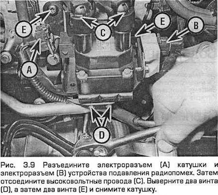
9. On pre-1998 models, remove the two screws securing the EGR pipe to the coil bracket. Then unscrew the fixing screws of the coil. Remove the coil assembly from the block head (see fig. 3.9).
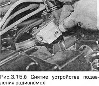
10. If necessary, the radio interference suppression device can be removed from the support bracket by unscrewing its bolts. Please note that the coil comes with the bracket as a single unit.
11. Installation - in the reverse order of removal. Make sure the high voltage spark plug wires are properly connected and securely tighten the coil screws.
Models with V-shaped 6-cylinder engines
Note: On V-6 models, the ignition coil is mounted on the rear head cover.
12. Disconnect the negative battery cable (chapter 5A).
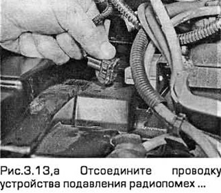
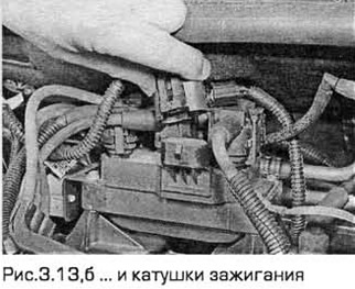
13. Disconnect the wiring from the ignition coil and radio interference suppression device. Free the wiring of these components from connections (see Fig. 3.1З, a, b). If necessary, remove the RVG valve solenoid from the top section of the intake manifold.
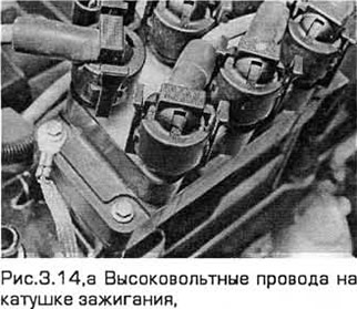
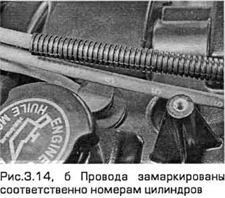
14. Disconnect high-voltage wires from the ignition coil, remembering their position. Squeezing the tabs of the stoppers, carefully remove the wires from the ignition coil. The wires are marked according to the cylinder numbers, (see Fig. 3.14, a, b).
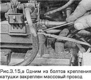
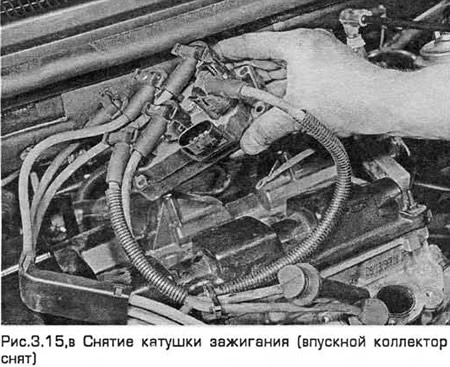
15. Remove the screws and remove the coil, taking into account that one of the bolts is fixed to the ground wire, and the other two bolts are fixed to the radio interference suppression device (see Fig. 3.15, a-c).
16. Installation - in the reverse order of removal. Make sure that the high voltage spark plug wires are properly connected and that one of the bolts is attached to the ground wire.
Visitor comments