The functional purpose of the fuel supply system is to ensure the supply of the required amount of fuel to the engine in all operating modes. The engine is equipped with an electronic control system with distributed fuel injection. In the distributed fuel injection system, the functions of mixture formation and metering of the fuel-air mixture supply to the engine cylinders are separated: the injectors perform metered fuel injection into the intake pipe, and the required amount of air at each moment of engine operation is supplied by the throttle unit. This control method makes it possible to ensure the optimal composition of the combustible mixture at each specific moment of engine operation, which allows obtaining maximum power with the lowest possible fuel consumption and low toxicity of exhaust gases. The fuel injection system and the ignition system are controlled by the electronic engine control unit (ECU), which continuously monitors the engine load, vehicle speed, thermal state of the engine, and the optimality of the combustion process in the cylinders using appropriate sensors.
The peculiarity of the injection system of the Ford Mondeo is the synchronicity of the injectors' operation in accordance with the valve timing (the engine control unit receives information from the phase sensors). The controller switches on the injectors sequentially, and not in pairs, as in asynchronous injection systems. Each injector is switched on after 720° of crankshaft rotation. However, in starting modes and dynamic engine operation modes, an asynchronous fuel supply method is used without synchronization with the crankshaft rotation.
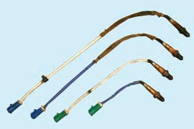
The main sensor for the fuel injection system is the exhaust gas oxygen concentration sensor (lambda probe).
In the exhaust manifold of 1.6 l engines, combined with two exhaust gas neutralizers (catalytic collector), two control oxygen concentration sensors are installed (separately for exhaust tracts 1 and 4, 2 and 3 cyl.), which, together with the engine control unit and injectors, form a control loop for the composition of the fuel-air mixture supplied to the engine. Based on the sensor signals, the engine control unit determines the amount of unburned oxygen in the exhaust gases and, accordingly, evaluates the optimality of the composition of the fuel-air mixture supplied to the engine cylinders at each moment in time. Having recorded a deviation of the composition from the optimal 1:14 (fuel and air, respectively), ensuring the most efficient operation of the exhaust gas catalytic neutralizers, the control unit changes the composition of the mixture using the injectors. Since the oxygen concentration sensors are included in the feedback circuit of the engine control unit, the control loop for the composition of the fuel-air mixture is closed. In addition to the two control sensors, there are also two diagnostic oxygen concentration sensors installed at the outlet of the neutralizers. Based on the composition of the gases that have passed through the neutralizers, they determine the efficiency of the engine management system. If the engine control unit, based on the information received from the diagnostic oxygen concentration sensors, records an excess of the exhaust gas toxicity standard that cannot be eliminated by calibrating the control system, it turns on the engine malfunction indicator lamp in the instrument cluster and stores the error code in memory for subsequent diagnostics.
In the catalytic converter of 2.0 and 2.3 l engines (with one neutralizer), one control and one diagnostic oxygen concentration sensor are installed.
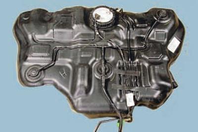
Fuel tank, molded from special impact-resistant plastic, is installed under the body floor in its rear part and secured with clamps. To prevent fuel vapors from entering the atmosphere, the tank is connected by a pipeline to the adsorber of the fuel vapor recovery system. An electric fuel pump is installed in the flange opening in the upper part of the tank, and on the right side there are branches for connecting the filler pipe and ventilation hose. From the pump, which includes coarse and fine fuel filters, fuel is fed into the fuel rail, secured to the engine intake pipe. From the fuel rail, fuel is injected by injectors into the intake pipe.
Fuel lines combined power supply systems in the form of interconnected steel pipelines and rubber hoses.
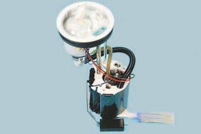
Fuel pump submersible, electric-driven, rotary type, with coarse and fine fuel filters, with a fuel pressure regulator. The pump is installed in the fuel tank, which reduces the possibility of vapor locks, since the fuel is supplied under pressure, and not under vacuum. The fuel pump supplies fuel from the fuel tank through the fuel line to the fuel rail under a pressure of about 380 kPa (approximately 360 kPa in idle mode).
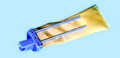
Fuel filter fine cleaning full-flow, installed in the fuel pump module housing. If the filter gets clogged, it can be replaced separately, as it is made easily removable.
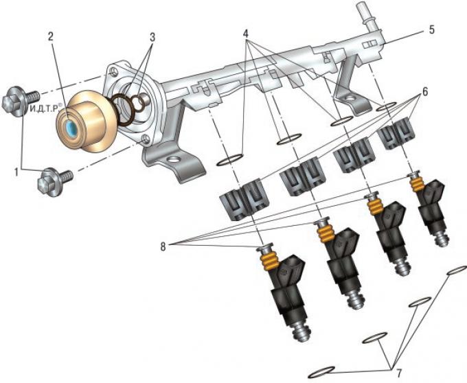
Fig. 5.62. Fuel rail with injectors and fuel pressure pulsation compensator of the Duratec Ti-VCТ engine with a volume of 1.6 l: 1 – fuel pressure pulsation compensator mounting bolts; 2 – fuel pressure pulsation compensator; 3 – fuel pressure pulsation compensator sealing rings; 4 – upper injector sealing rings; 5 – fuel rail; 6 – injector retainers; 7 – lower injector sealing rings; 8 – injectors.
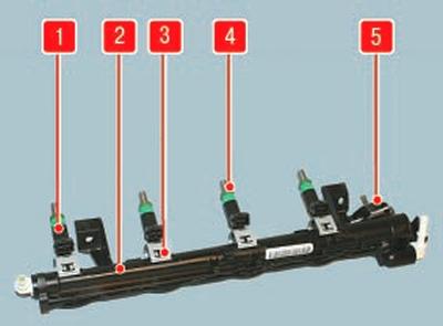
Fig. 5.63. Fuel rail with injectors and fuel pressure regulator of 1.6 l Duratec Ti-VCT engines: 1 – injector; 2 – ramp; 3 – nozzle retainer; 4 – injector sealing ring; 5 – fuel pressure regulator.
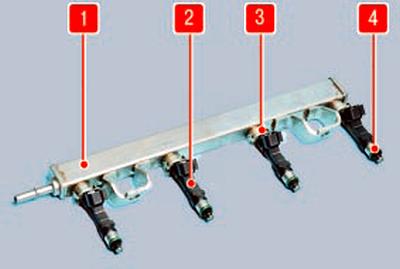
Fig. 5.64. Fuel rail with injectors and fuel pressure regulator of Duratec-HE engines with a volume of 2.0 and 2.3 l: 1 – rail; 2 – nozzle; 3 – nozzle retainer; 4 – injector sealing ring.
Fuel rail (Fig. 5.62–5.64), which is a hollow tubular part with holes for installing injectors, serves to supply fuel to the injectors and is secured to the intake manifold. A compensator 2 (see Fig. 5.62) for fuel pressure pulsations is also installed on the fuel rail of the 1.6 l Duratec Ti-VCT engine, and a regulator 5 (see Fig. 5.63) for fuel pressure is installed on the 1.6 l Duratec-HE engines. The injectors, pressure pulsation compensator and pressure regulator are sealed in their seats with rubber rings.
The ramp with the injectors in assembly is inserted with the injector tails into the holes of the intake manifold and secured with two nuts.
NOTE: Depending on the design version, the fuel pressure pulsation compensator may not have a small sealing ring 3 (see Fig. 5.62).
Nozzles with their sprayers enter the holes of the intake pipe. In the holes of the intake pipe, the sprayers are sealed with rubber sealing rings. The sprayer is designed for metered injection of fuel into the engine cylinder and is a high-precision electromechanical valve in which the needle of the shut-off valve is pressed to the seat by a spring. When an electrical impulse is supplied from the control unit to the winding of the electromagnet, the needle rises and opens the sprayer hole - fuel is supplied to the intake pipe of the engine. The amount of fuel injected by the sprayer depends on the duration of the electrical impulse.
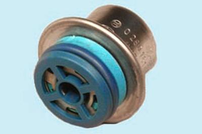
Pulsation compensator the fuel pressure switch is installed on the 1.6L Duratec Ti-VCT (variable valve timing) engine at the end of the fuel rail and serves to maintain constant fuel pressure in the rail when there is a sharp drop in fuel pressure in the fuel line, caused, for example, by a significant increase in fuel consumption during intensive acceleration of the car.
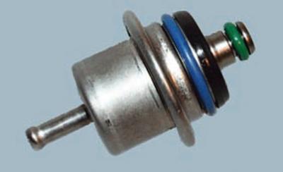
Fuel pressure regulator, installed on the 1.6 l Duratec-HE engines on the fuel rail, and on the other engines on the fuel pump, maintains constant fuel pressure in the central channel of the rail in all engine operating modes. Regulation of the fuel pressure supplied to the injectors by the regulator installed on the fuel rail is based on the principle of monitoring the pressure difference in the rail and the intake manifold, which under any conditions should be at least 300 kPa (3 kgf/cm²). The supply of the electric fuel pump is greater than necessary to ensure the operability of the system. Therefore, when the engine is running, with the help of the pressure regulator, some of the fuel is constantly drained through the return line into the fuel tank. Depending on the vacuum in the intake manifold, the pressure regulator reduces or increases the drain of excess fuel, maintaining a constant pressure in the rail.
The pressure regulator is a closed cavity divided by a diaphragm into a vacuum and fuel chamber.
The vacuum chamber communicates with the engine intake manifold through a vacuum hose, the fuel chamber – through a channel in the regulator body with the cavity of the fuel rail. During engine operation, the regulator valve is closed under the action of the spring if the pressure difference in the intake manifold and the fuel rail is no more than 0.3 MPa. There is no backflow of fuel – the pressure in the fuel line begins to increase. When the pressure difference exceeds 300 kPa (3.0 kgf/cm²), the regulator diaphragm bends and a gap is formed between the valve and its seat, through which excess fuel is drained into another channel of the regulator connected to the drain pipe – the pressure decreases. With an increase in the load of the engine, operating with a large opening of the throttle valve, fuel consumption increases and the pressure in the fuel rail drops. At the same time, the vacuum in the intake pipe decreases. The spring presses the pressure regulator valve to the seat, the fuel drain into the fuel tank stops - the pressure increases. These processes are repeated continuously, as a result of which a constant pressure is maintained in the fuel rail.
The pressure regulator installed in the fuel pump module is a precisely calibrated bypass valve, the shut-off element of which opens when a specified pressure is reached in the pressure pipeline inside the module, as a result of which excess fuel is drained into the tank directly from the fuel pump module, and the design does not include a return line from the fuel rail.
Air filter is installed on the left side of the engine compartment on a special bracket. The filter element is paper, flat, with a large filter surface area. The filter is connected by a rubber corrugated air supply sleeve to the throttle assembly.
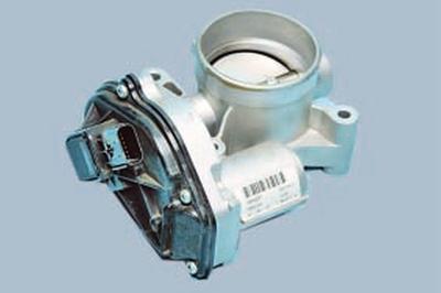
Throttle assembly, which is a simple control device, serves to change the amount of main air supplied to the engine intake system, is installed on the inlet flange of the intake pipe and secured with screws.
A molded rubber sleeve is placed on the inlet pipe of the throttle assembly, secured with a clamp and connecting the throttle assembly to the air filter.
The throttle assembly includes a throttle position sensor and a stepper motor for controlling the throttle valve. There is no mechanical connection between the throttle assembly and the throttle valve control pedal. The so-called "electronic" throttle valve control pedal transmits information about the degree of pressure on the pedal to the electronic engine control unit, which, in turn, taking into account the vehicle speed, the gear engaged, the engine load and the crankshaft speed, opens the throttle valve to the required angle.
Fuel vapor recovery system prevents fuel vapors from escaping from the fuel system into the atmosphere, which have an adverse effect on the environment.
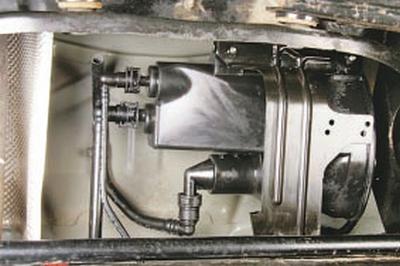
The system uses a method of vapor absorption by a carbon adsorber. It is installed in the rear part of the body base and is connected by pipelines to the fuel tank and the purge valve.
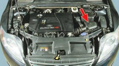
In the engine compartment there is an electromagnetic valve for purging the adsorber, which switches the operating modes of the system based on signals from the engine control unit.
Fuel vapors from the fuel tank are constantly removed through a pipeline and accumulate in the adsorber filled with activated carbon (adsorbent). When the engine is running, the adsorbent is regenerated (restored) by purging the adsorber with fresh air entering the system under the action of vacuum transmitted through the pipeline from the inlet pipe to the adsorber cavity when the purge valve opens.
The control unit regulates the degree of purge of the adsorber depending on the engine operating mode, sending a signal with a variable pulse frequency to the valve.
Fuel vapors from the adsorber enter the engine intake pipe through a pipeline and burn in the cylinders.
Malfunctions of the fuel vapor recovery system lead to unstable idle speed, engine stalling, increased toxicity of exhaust gases and deterioration of the vehicle's driving performance.