This section only briefly describes the malfunctions of the injection system caused by the failure of certain sensors. The procedure for removing and installing components of the power supply and engine control systems is given in subsections "Power supply system", p. 127 and "Engine management system", p. 225.
In the feedback injection system, an exhaust gas catalytic converter and an oxygen concentration sensor in the exhaust gases are installed, which provides feedback. The sensor monitors the oxygen concentration in the exhaust gases, and the electronic control unit, using its signals, maintains such an air-fuel ratio at which the converter works most efficiently.
WARNING: Before removing any parts of the fuel injection system, disconnect the wire from the negative terminal of the battery.
WARNING: Disconnect the battery only when the ignition is off.
WARNING: Do not start the engine if the cable lugs on the battery are loose.
WARNING: Never disconnect the battery from the vehicle's electrical system while the engine is running.
WARNING: When charging, disconnect the battery from the car's on-board network, as increased current during charging can damage electronic components.
WARNING: Avoid heating the electronic control box (ECU) above 65°C in working condition and above 80°C - in non-working condition (e.g. in a drying chamber). It is necessary to remove the computer from the car if this temperature is exceeded.
WARNING: Do not disconnect or connect wiring harness connectors to the ECU while the ignition is on.
WARNING: Disconnect the wires from the battery and the wire connectors from the ECU before arc welding on the vehicle.
WARNING: Make all voltage measurements with a digital voltmeter with an internal resistance of at least 10 MΩ.
WARNING: The electronic components used in the injection system are designed for very low voltage and can easily be damaged by electrostatic discharge. In order to prevent damage to the ECU by electrostatic discharge: – do not touch the ECU plugs or electronic components on its boards with your hands; – when working with programmable read-only memory (PROM) control unit, do not touch the microcircuit pins.
WARNING: It is not allowed to run an engine with a catalytic converter on leaded gasoline - this will lead to a quick failure of the catalytic converter and the oxygen concentration sensor.
WARNING: When operating in rainy weather, do not allow water to come into contact with the electronic components of the fuel injection system.
The vast majority of fuel injection system malfunctions are caused by the failure of the following sensors:
- crankshaft position sensor - complete failure of the injection system, the engine does not start;
- phase sensor - power reduction, increase in fuel consumption;
– absolute pressure sensor (rarefaction) in the intake pipe - an increase in fuel consumption, a significant deterioration in dynamics, problems with starting the engine;
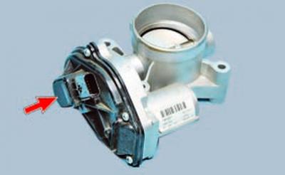
- throttle position sensor - loss of power, jerks and dips during acceleration, unstable idling;
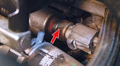
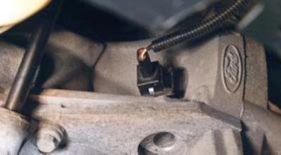
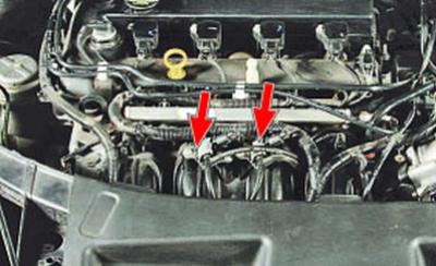
– coolant temperature sensor (mounted on the right side of the cylinder head under the intake pipe, intake pipe support bracket removed for clarity) - difficulties with starting in cold weather: you have to warm up the engine, maintaining the speed with the accelerator pedal, when overheating, power is significantly reduced, detonation appears;
– intake air temperature sensor – increase in fuel consumption, increase in the level of toxicity of exhaust gases;
– oxygen concentration sensor (Lambda probe) – Increased fuel consumption, reduced engine power, unstable idling. Possibly damaged catalytic converter.
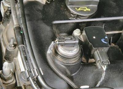
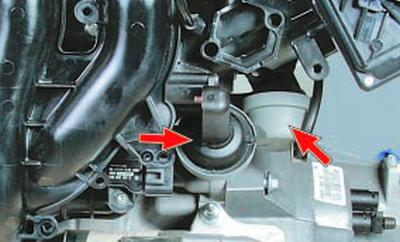
– solenoid valve of the variable valve timing system (installed only on engines with a volume of 1.6; 2.3 and 2.5 liters VCT - in the event of a valve failure, a significant deterioration in dynamics and "swimming" of the crankshaft speed at idle until the engine stops completely;
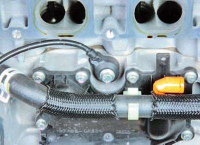
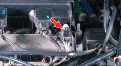
- knock sensor (installed on the right side of the cylinder block in the region of the 2nd and 3rd cylinders) - the engine is very sensitive to the quality of gasoline, increased tendency to detonation;
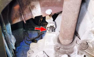
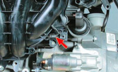
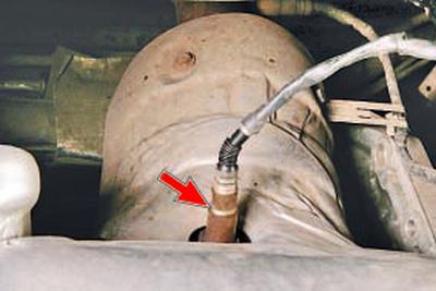
– speed sensor (mounted on the gearbox housing) – possible deterioration of the dynamic qualities of the car and an increase in fuel consumption;
- solenoid valves..
... and pneumatic actuators of the system for changing the geometry of the intake pipe - the deterioration of the dynamic qualities of the car and the increase in fuel consumption are possible.
Visitor comments