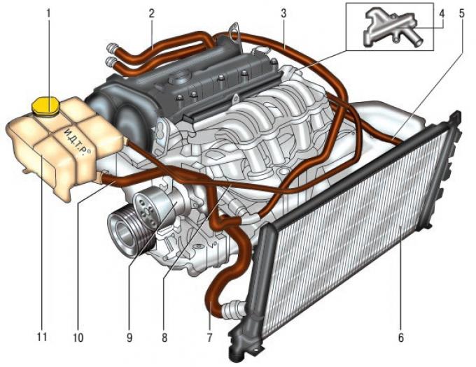
Fig. 5.58. Cooling system: 1 – expansion tank cap; 2 – heater supply hose; 3 – heater outlet hose; 4 – distributor housing; 5 – radiator supply hose; 6 – radiator; 7 – radiator drain hose; 8 – expansion tank steam outlet hose; 9 – water pump; 10 – liquid hose of the expansion tank; 11 – expansion tank.
The engine cooling system is liquid, closed type, with forced circulation of liquid. The design of the cooling system is shown in Fig. 5.58. The system consists of a cooling jacket, radiator 6 with an electric fan, expansion tank 11, water pump 9, thermostat, water jacket outlet pipe and hoses.
The water pump creates the circulation of liquid in the system. From the pump, the liquid is fed into the engine cooling jacket, washes the cylinders of the combustion chamber and then goes to the thermostat. Depending on the position of the thermostat valve, the liquid goes either to the water pump (at low temperatures) or to the radiator (at high temperatures).
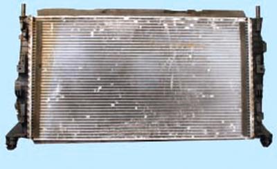
Radiator with horizontal liquid flow, with a tubular-ribbon aluminum core and plastic tanks.
At the bottom of the left radiator tank there is a drain plug. The tanks contain the supply and return hose pipes to the engine water jacket, and the steam hose pipe connecting the radiator to the expansion tank.
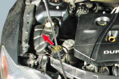
Expansion tank serves to compensate for the changing volume of the coolant depending on its temperature. It is made of translucent plastic. The plastic cap of the tank, which closes its neck, contains the inlet and outlet valves.
NOTE: The serviceability of the expansion tank cap valves is very important for the normal operation of the cooling system. However, when problems arise (for example, boiling coolant), car enthusiasts pay attention only to the operation of the thermostat and forget to check the valves.
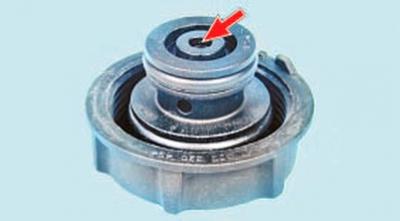
A leaky outlet valve leads to a decrease in the boiling point of the coolant, and its jamming in the closed position leads to an emergency increase in pressure in the system, which can cause damage to the radiator and hoses.
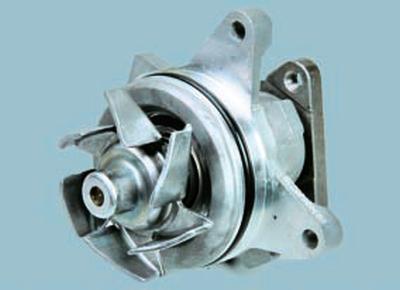
Water pump centrifugal type provides forced circulation of liquid in the cooling system. It is located on the front surface of the cylinder block and is driven from the crankshaft pulley by a poly V-belt, common with the generator and the power steering pump. The pump has sealed bearings that do not require replenishment of lubricant. The pump is not subject to repair, therefore, in case of failure (fluid leakage or damage to the bearings), it is replaced as an assembly.
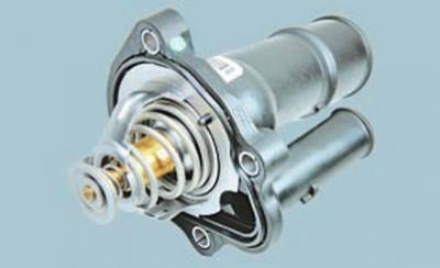
Thermostat, which is an electromagnetic valve, maintains the normal operating temperature of the coolant and reduces the engine warm-up time.
The thermostat is controlled by the electronic engine management system unit, which receives information from the coolant temperature sensor installed on the outlet pipe of the water jacket. The thermostat is installed in a housing fixed to the cylinder head. At a coolant temperature of up to 60°C, the thermostat is completely closed and the liquid circulates along a small circuit, bypassing the radiator, which accelerates engine warm-up. At a temperature of about 80°C, the thermostat begins to open, and at 98°C it opens completely, ensuring circulation of liquid through the radiator.
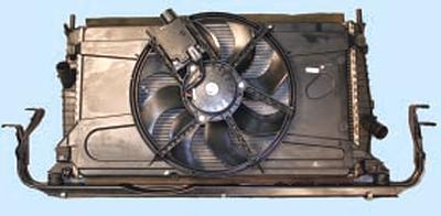
Electric fan cooling system (with a plastic eight-blade impeller) serves for additional blowing of the radiator, is switched on and off by a signal from the electronic engine control unit. Moreover, depending on the intensity of the thermal mode and the algorithm of the air conditioner, the electric fan can rotate at low and high speed. Changing the fan speed mode is ensured by the engine control unit by connecting an additional resistor. The electric fan assembled with the casing is fixed on the radiator of the cooling system.
Water jacket outlet pipe serves to distribute coolant flows depending on the operating modes of the cooling system. A coolant temperature sensor is screwed into the body of the pipe, based on the information from which the electronic unit of the engine control system controls the thermal mode of the engine.
Shut-off valve (not installed on Duratec-HE engines) is designed to stop the coolant draining into the expansion tank when starting a cold engine. The shut-off valve in the closed state reduces the coolant circulation in the system of an unheated engine, which saves fuel when warming up the engine and reduces the warm-up time. At a coolant temperature of 80°C, the shut-off valve opens completely and the liquid begins to circulate through the expansion tank.
The interior heater radiator is also connected to the cooling system via hoses.
The system is filled with a liquid (antifreeze) that does not freeze at ambient temperatures down to -40°C. The type of coolant poured into the cooling system is Motorcraft Super Plus 4 (green) or Motorcraft Super Plus 2000 (orange).
WARNING: Motorcraft Super Plus 4 non-silicified organic acid (OAT) coolant should not be mixed with other types of coolant.
Motorcraft Super Plus 2000 is a monoethylene glycol based coolant, like most modern coolants.
WARNING: It is not recommended to fill the cooling system with water, as the antifreeze contains anti-corrosion, anti-foaming and anti-scale additives.
Coolant is toxic! Avoid inhaling its vapors and contact with skin.
Repair any leaks in the cooling system promptly to prevent coolant vapors from entering the vehicle's interior during operation.
Your health is more valuable than a new cooling system hose or a tube of sealant! The electronic engine control unit has a program to protect the engine from overheating. At the very beginning of overheating, based on information from the coolant temperature sensor, the engine control unit sends a command to move the coolant temperature indicator needle to the red zone.
If the driver does not stop the engine and its temperature continues to rise, the engine control unit turns on a warning light, which warns the driver that the engine is approaching a critical limit and must be stopped.
If the driver ignores the coolant temperature gauge and the warning light, the engine control unit cuts off the fuel supply to two engine cylinders and limits the crankshaft speed to 3000 min⁻¹.
At the same time, the engine malfunction indicator lamp lights up, indicating the possibility of significant engine damage and a sharp increase in exhaust toxicity. In this mode, air is sucked into the disabled cylinders, which allows the engine temperature to be reduced. Moreover, the disabled cylinders alternate with each other for more uniform cooling.
NOTE: If the engine has entered the two-cylinder mode, the only way to return it to four-cylinder mode is to turn the ignition off and then back on.
If the engine temperature continues to rise after all measures have been taken, the control unit stops the engine. If at this time the throttle control pedal has moved to a large angle by pressing the foot (for example, the driver is overtaking), the engine will be stopped only 10 seconds after releasing the pedal.
The original source of this article can be found at fordbook.ru