If there is a malfunction in the electrical equipment, or it is necessary to additionally install an electric unit, then in this case you cannot do without electrical circuits. The electrical circuits shown in the circuits must be closed, otherwise the electric current will not flow. For example, it is not enough to apply voltage to the positive contact of the headlight, you also need to connect the electrical circuit to the "ground".
Therefore, the battery ground wire is also connected to the body. However, this connection to the ground is not enough, and the corresponding current consumers have a direct connection wire to the ground with brown insulation. Switches, relays, fuses, measuring devices, electric motors and other electrical elements can be included in individual electrical circuits. In order to correctly connect the electrical elements, their individual contacts have corresponding terminal designations. To navigate when working with the diagrams, individual current circuits are located vertically next to each other.
The electrical diagram shows the positive contacts (+) of the current circuit at the top, and the ground contacts at the bottom. The connection to the ground is usually made directly through the car body or through an additional wire from the ground connection point located on the body.
Attention! The image of electrical elements and wires in the diagrams is not scaled. For example, a wire longer than a meter is shown in the diagram in the same way as a wire several centimeters long. In addition, the connections inside complex electrical elements are presented in a simplified manner.
The most important terminals
Terminal 15 is powered by the ignition switch. Current flows only when the ignition is on. The wire is usually green or green with colored stripes.
Terminal 30. Battery voltage is always applied to this terminal. The wire is usually red or has colored stripes.
Terminal 31 connected to the "ground". The "ground" wires are usually black.
In electrical diagrams, individual wires are designated using a combination of letters and numbers.
Example: 31S - ASZA/1.5 BK/RD
31 = terminal 31 ="ground" (-)
S = additional power cable included (not serial)
AC = system (AC = adjustable lighting range)
ZA = connection: 3 = wire number, A = branch designation
1.5 = 1.5 mm²
BK = primary color (BK = black)
/RD = marking color (RD = red)
Abbreviated symbols for the colors of electrical wires in diagrams
- VK = black
- GY = gray
- BN = brown
- LG = light green
- BU = blue
- OG = orange
- GN = green
- RD = red
- SR = silver
- WH = white
- VT = purple
- YE = yellow
Heated seats
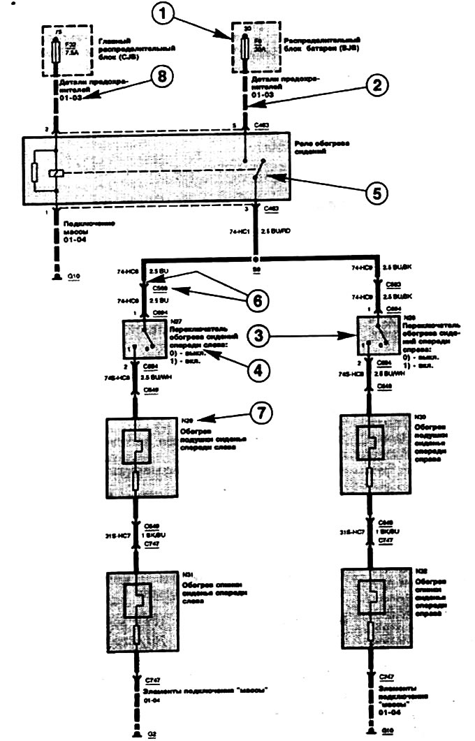
1 - Shaded block. Represents a partially depicted electrical unit.
2 - Broken line. Indicates two or more electric drives.
3 - Switch. Always shown in its initial state (off).
4 - Notes: Provide additional information on individual electrical components.
5 - Electrical element: Here is a relay. In the electrical element, the power switch is indicated to explain its function.
6 - Connector. CN is the connector designation.
7 - Designation of the electrical element.
8 - Link to additional FORD diagrams. No picture
9 - Curved bracket. The curly bracket indicates the difference between individual equipment variants.
10 - Triangle at the beginning of the electrical wire: Indicates the transition of the connection from one electrical circuit to another (the digital code indicates the internal FORD designation).
11 - Curved dividing line: The electrical element is located in the following diagram.
(Content was created using data from this website: fordbook.ru)