


OHV engine
Engine Crankcase Ventilation System OHV
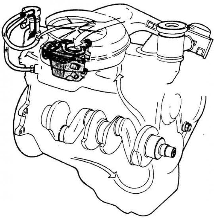
Internal view of the oil cap
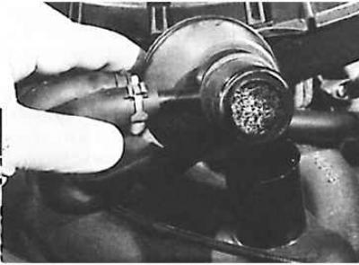 |
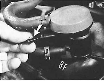 |
The tube with the calibrated hole (indicated by the arrow in the figure on the right) must always be clean.
To improve the efficiency of ventilation at idle speed and with the throttle valve partially open, fresh air partially enters the upper part of the oil filler plug through a wire filter, mixes with crankcase gases, is fed through a hose into the intake manifold and is burned.
In the full throttle mode, crankcase gases are additionally sucked out through the carburetor. The distribution of gas flows is determined by the diameter of the hole in the oil filler plug, the size of which corresponds to a certain type of engine.
On early engine models, all crankcase ventilation hoses connected to the oil filler plug, with the lower hose providing fresh air directly into the crankcase.
The wire filter of the crater ventilation system, located in the oil filler plug, must be washed every 20,000 km of the vehicle's mileage.
CVH engine with carburetor
Crankcase ventilation system CVH
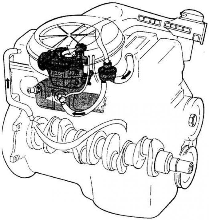
The engine crankcase is ventilated through a valve installed in the lower part of the air filter housing. The valve must be replaced every 40,000 km of vehicle mileage.
CVH engine with injector
The engine crankcase ventilation is carried out by direct connection of the crankcase with the intake manifold. The valve installed on the crankcase must be replaced every 40,000 km of vehicle mileage.
Diesel engine
Diesel engine crankcase ventilation system
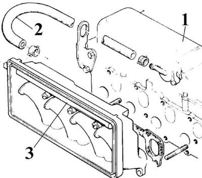
1 – cylinder head cover; 2 – hose; 3 – tube with calibrated holes
The check valve on the cylinder head cover and the tube in the intake manifold are connected by a hose. The tube has 4 calibrated holes that are located opposite the intake channels, and through these holes the crankcase gases are removed, which simultaneously lubricate the intake valves.
(The original version can be found on the website: fordbook)