Contents: Removal ↳ Adjusting the float level ↳
Removal
Remove the negative terminal from the battery. Remove the air filter.
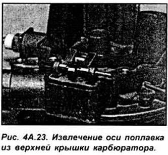
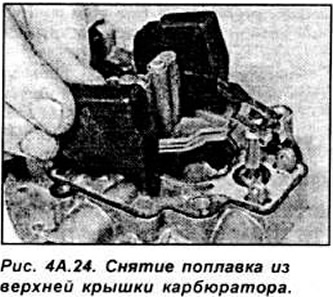
Carefully clean all external dirt from the carburetor, disconnect the fuel supply and return hoses from the carburetor, having marked them beforehand. Close the ends of the hoses with plugs. Disconnect the wires from the electromagnetic anti-knock valve. Remove the air damper control cable. Unscrew the 6 mounting screws (4 of which are TORX type) and, being careful, lift the upper cover of the carburetor. Turn the carburetor cover over to access the float and remove the float mounting axis from the upper cover of the carburetor, carefully tapping it if necessary. Remove the float (see Fig. 4A.23, 4A.24).
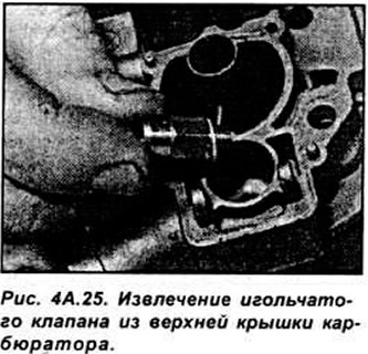
Unscrew the needle valve housing and remove it from the carburetor top cover. Remove the needle valve gasket from the carburetor top cover (see Fig. 4A.25).
Check components for damage and replace if necessary. Check the needle valve for wear and the float for leaks. Clean the float chamber.
Place a new gasket on the needle valve and carefully screw it into the cap.
When installing the float and needle valve, make sure the float tab is positioned under the spring clip on the needle valve. Reinstall the float shaft.
Check and, if necessary, adjust the float level.
After ensuring that the mating surfaces of the carburetor and carburetor cover are clean, install a new gasket onto the carburetor body and onto the carburetor cover.
Reconnect the fuel hoses and the anti-knock valve electrical connector, as well as the choke cable. If any of the hoses were originally secured with twist-off clamps, remove them and replace with standard hose clamps.
Install the air filter.
Connect the negative terminal to the battery, start the engine and check the mixture quality and idle speed.
Adjusting the float level
Install a new gasket on the carburetor cover, then install the cover vertically with the needle valve in the uppermost position and closed.
Measure the distance between the top cover gaskets and the bottom of the float (see Fig. 4A.26).
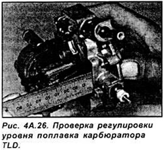
If the distance is not as required, adjust it by bending the protrusion on the float assembly.