Attention! Do not use tools that could scratch the parts to be cleaned.
1. Using a ruler, check the flatness of the lower plane of the cylinder head along, across and diagonally.
2. Check the condition of the valve guides.
3. Check the condition of the valve seats.
4. Check the condition of the axis of the valve levers and the surface of the levers in contact with the ends of the valve stems for wear and the presence of scratches and scratches.
5. Check the condition of the valve springs. Springs must be replaced after 80,000 km of vehicle run.
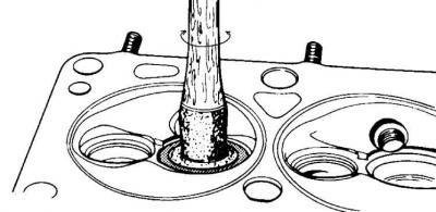
Checking the valve guides
6. Worn valve guides do not align the valves in their seats, resulting in a significant increase in fuel and oil consumption.
7. Insert the valve into the guide sleeve and, moving the valve in the transverse direction, check the clearance.
8. If the gap exceeds the allowable limits, it is necessary to machine the guide bush using an appropriate reamer to the next enlarged size. The processing of the guide sleeve must be started from the side of the combustion chamber.
Processing of valve seats in the cylinder head
9. Valve seats with signs of wear or burning must be processed with the obligatory preservation of angles and chamfers. Otherwise, it is necessary to replace the cylinder head. After any processing of valve seats, it is necessary to grind the valves.
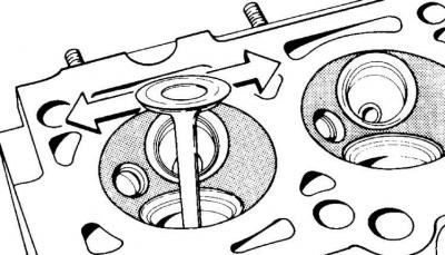
Lapping of valves
10. Lapping machined valve seats. The valves should be lapped using only fine-grained polishing paste.
11. Lubricate the surface of the valve seat with a small amount of paste and install the valve in the appropriate seat. Firmly press the rubber suction cup against the valve plate and rotate the valve in one direction or the other.
12. After the end of the lapping process, thoroughly clean all parts from dirt and paste and check the valve seat and disc. A solid opaque ring should be visible on both parts, which indicates the width of the valve chamfer.
13. Draw strokes on the valve disc ring with a pencil at a distance of about 1 mm evenly around the circumference, then insert the valve into the guide sleeve and turn it 90°, while slightly pressing the valve.
14. Take out the valve and check for streaks. If all strokes are erased, the valve can be finally installed. Otherwise, the lapping operation must be repeated.
Valve linkage
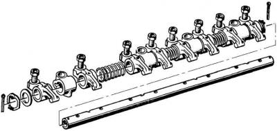
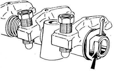
15. Remove the cotter pin, fixing plate and washer from one side of the axle. Sequentially remove the levers, support legs and springs from the axle, keeping their location for subsequent assembly in the same order in which they were removed.
16. Clean the oil supply holes.
17. Lubricate the axle with oil before assembly.
18. The flat on the end of the axle should be on the side of the valve clearance adjustment bolts, which ensures normal lubrication of the rubbing parts of the lever mechanism.
Visitor comments