2. Install the camshaft mounting plate and check its axial play.
3. Install the pushers in their original places.
4. Install and secure the main bearing shells and thrust half rings with grease so that the grease grooves face the crankshaft.
5. Install the woodruff key and sprocket onto the crankshaft.
6. Lubricate the crankshaft main journals with engine oil and install it into the cylinder block.
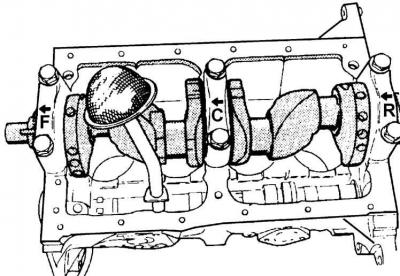
7. Install the main bearing caps with liners in accordance with the markings and tighten the bolts.
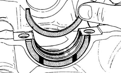
8. Check the axial movement of the crankshaft using a dial indicator. If the movement exceeds the permissible limits, it is necessary to install thicker thrust half rings.
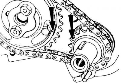
9. Turn the crankshaft to such a position that the mark on the sprocket is on the line connecting the axes of the camshaft and crankshaft (the marks on the camshaft and crankshaft are indicated by arrows).
10. Install the drive chain on the crankshaft sprocket and camshaft sprocket, screw the sprocket to the camshaft flange. The bolt holes on the sprocket must match the holes on the camshaft flange, and the timing marks must be facing each other. You may have to turn the camshaft to align the bolt holes. Secure the bolts from unscrewing by bending the tabs of the locking plate.
11. Install the chain tensioner.
12. Install the oil deflector ring on the crankshaft sprocket side so that its convex side faces the sprocket.
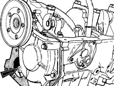
13. Screw on the drive cover with a new gasket and a new sealing ring pre-installed. Do not screw in one bolt (indicated by the arrow) securing the cover until the water pump is installed.
14. Install the water pump.
15. Lubricate the working edges of the sealing ring, install the crankshaft pulley and tighten the mounting bolt.
16. Install the crankshaft rear seal cover and tighten the bolts.
17. Install the rear shield on the cylinder block.
18. Install the flywheel on the crankshaft and screw it in place.
19. Install the clutch, having first centered it.
20. Lubricate the cylinders and install the pistons with rings and connecting rods. The arrows on the pistons should point toward the timing drive, and the oil channel holes on the connecting rods should be on the left. Screw on the connecting rod caps.
21. Install the oil pan and drain plug.
22. Install the oil pressure sensor.
23. Turning the crankshaft, set the piston of the first cylinder to TDC, while the marks on the crankshaft pulley and on the drive cover must match. Install the oil pump with filter.
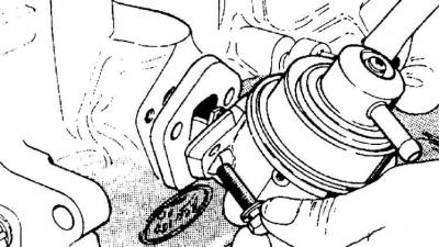
24. Install the fuel pump.
25. Install the cylinder head.
26. Install the pushers in the same places where they were.
27. Install the axle with levers on the head.
28. Adjust valve clearances.
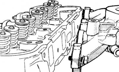
29. Install the intake (shown) and exhaust manifolds.
30. Install the carburetor and connect the fuel line from the fuel pump.
31. Install the spark plugs and coolant temperature sensor.
32. Install the thermostat and thermostat housing cover.
33. Install the water pump pulley.
34. Install the generator, put on the drive belt and adjust its tension.
35. Install the ignition distributor.
36. Install the distributor cap and connect the high-voltage wires to the spark plugs.
37. Install the coolant hose located on the side of the engine.
38. Install the crankcase ventilation hose to the intake manifold and oil filler cap.
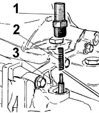
39. Screw the gearbox to the engine and check that the locking pin (1) of the gear selector shaft is installed together with the spring (2) and pin (3).
(The text is available on the specified website info portal: FORDBOOK)