Device Features
Single-chamber with a falling flow and a variable diffuser section, has a main dosing system, an idle system, a diaphragm accelerator pump, an automatic starter (from July 1983 manual starter on all models except LPA) l Idle system solenoid shut-off valve (pic. 2.77).
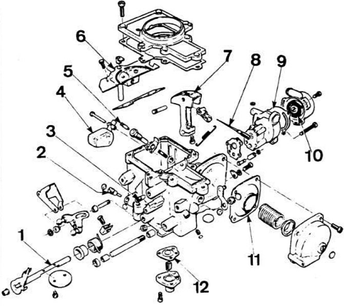 Pic. 2.77. Ford carburetor parts.
1 - throttle axis; 2 - mixture quality screw; 3 - adjusting screw of the bypass channel; 4 - float; 5 - needle valve; 6 - fuel jet of the main metering system; 7 - air valve; 8 - dosing needle; 9 - automatic starting device; 10 - bimetallic spring; 11 - valve control diaphragm; 12 - accelerator pump diaphragm.
The carburetor has a float chamber and a diffuser, the flow section of which depends on the vacuum above the pneumatic drive diaphragm. Vacuum in front of the throttle valve created by the engine. determines the amount of opening of the diffuser damper. Depending on the steady section of the diffuser, the metering needle regulates the flow area of the main fuel jet. The diffuser valve and the dosing needle are kinematically connected to each other. The flow section of the main fuel jet and the conical sections of the metering needle are made with high precision. are a matched pair and are not dismantled in operation.
The principle of operation of the main dosing system
The main metering system includes the main fuel jet, compensation jet and conical needle Fuel flows from the carburetor float chamber to the main fuel jet and enters the diffuser along the annular section between the walls of the jet and the needle The air flow rate remains constant, providing the necessary atomization of gasoline at all engine operating modes. Improved fuel atomization ensures stable operation of the engine on a lean mixture while maintaining engine power and reducing the CO content in the exhaust gases. At low engine speeds, the metering needle connected to the valve closes the main fuel jet almost completely.
As the load on the engine increases, the degree of vacuum in the diffuser and above the diaphragm of the pneumatic actuator also increases, this increases the opening of the valve. In this case, the valve acts on the metering needle located in the main fuel and compensation jets. Moving the metering needle increases the opening of the main fuel jet, i.e. more fuel enters the engine. The metering needle is made in such a way and with such accuracy that under any load on the engine, a strictly defined amount of fuel enters it. Changing the shape of the needle is not allowed.
In idle mode, when the engine consumes small volumes of air, the valve is held in its original position by the diaphragm return spring, the carburetor throttle is closed. the control vacuum is small.
When the throttle is opened, the vacuum increases, which affects the diaphragm of the pneumatic actuator (vacuum regulator), which, compressing the return spring, opens the valve until a balance is established between the force of the return spring and the control vacuum.
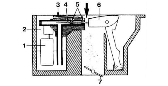 Pic. 2.78. The principle of operation of a carburetor with a variable diffuser section.
1 - float; 2 - float chamber; 3 - bypass channel; 4 - dosing needle; 5 - main and auxiliary jets; 6 - air spool; 7 - throttle valve. The arrow indicates the air intake.
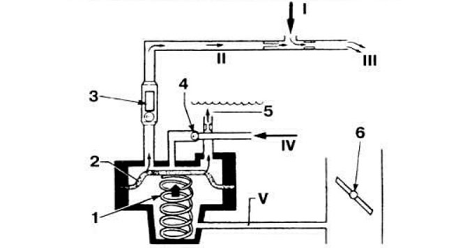 Pic. 2.79. Fuel supply by accelerator pump.
1 - diaphragm spring; 2 - diaphragm; 3 - discharge valve; 4 - inlet valve; 5 — removal of vapors of gasoline; 6 - throttle valve; I - Air; II - Gasoline; III - Fuel-air mixture; IV - Fuel supply; V - Vacuum supply channel.
Visitor comments