Adjustment of idling and CO content in exhaust gases
Warm up the engine to operating temperature, connect the gas analyzer and tachometer. Set the crankshaft speed to 3000 rpm, hold it for about 30 seconds and reset the speed to idling speed. After the arrows of the instruments calm down, take readings of the CO content and the crankshaft speed. If necessary, adjust the speed with a screw of quantity 1 (pic. 2.80).
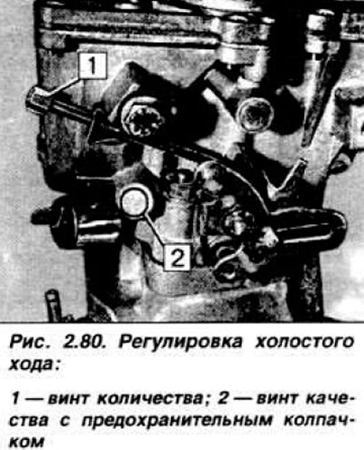
In case of high CO content, remove the safety cap 2 quality screws with a narrow-bladed screwdriver. Raise the speed to 3000 rpm, reset it to idle and within 30 seconds, by turning the quality screw, adjust the CO content in the exhaust gases. If the adjustment took more than 30 seconds, repeat the operation. Install a new safety cap on the quality screw.
Adjustment of idling and CO content in the exhaust gases of engines with automatic transmission
Loosen the downshift adjustment screw (see fig. In chapter «Hydromechanical gearbox») so as to obtain a gap of 2-3 mm Set the selector lever to the position «R» and warm up the engine to operating temperature and apply the handbrake. Adjust idle speed (850 rpm) and CO content (1,5%) with the electric fan running. Set the clearance of 0.1 mm with the adjusting screw of the forced downshift mechanism. paying attention to the free rotation of the actuator axis of the control valve. Recheck idle speed and CO content.
Adjustment of the automatic starter
Disconnect the negative cable from the battery and remove the air filter. Unscrew the three cross-head screws securing the bimetal spring housing to the automatic trigger housing and remove it. Remove the adjustment hole plug from the top of the starter housing. Turn the lever of the bimetallic spring of the starting device so. so that the center hole of the axle is aligned with the hole of the plug (pic. 2.81).
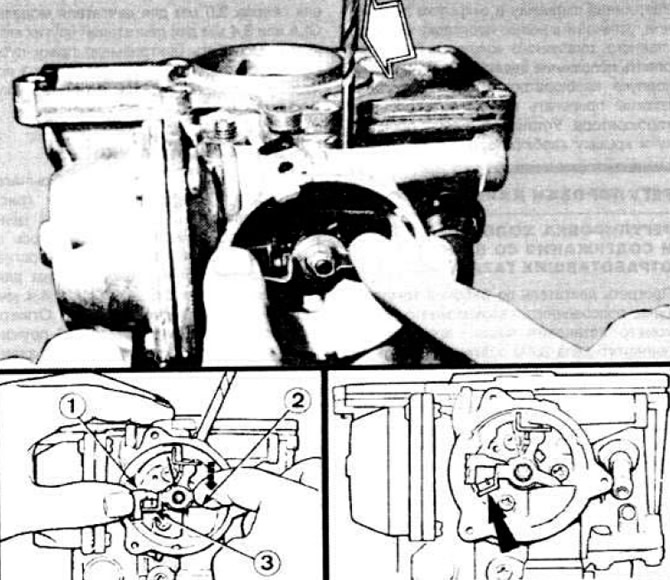 Pic. 2.81. Adjustment of the automatic starting device without removal from the carburetor.
1 - the lever of the bimetallic spring, held in the pressed position; 2 - the plunger of the starting device is recessed down to the stop; 3 - the opening lever is pressed against the lever of the bimetallic spring. The arrow shows the tongue of the ajar lever.
Check through the opening of the protective plug. Insert a 3.0 mm drill shank for the GLA engine or 3.4 mm for other engine models into the axle hole. Loosen the central nut of the trigger and turn lever 1 clockwise until it stops, tighten the nut and remove the drill.
Air flap adjustment
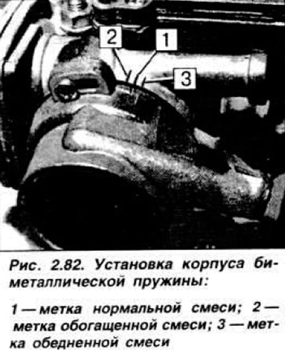
Using tweezers, bend down the tongue of the lever to slightly open the air damper (pic. 2.81) and turn it so that the central hole of the axle is aligned with the hole of the plug, insert the drill shank 3.3 mm for GLA and LUA engines and 4.4 mm for engines of other models into the hole until it stops. Press the lever of the bimetallic spring to the stop clockwise or counterclockwise, depending on the engine model, to access the pneumatic drive plunger and drown it. In this position, there must be a gap between the opening lever and the bimetal spring lever. Holding lever 1 (pic. 2.81) of the bimetallic spring pressed clockwise to the stop, bend the tongue of the opening lever 3 until it touches the lever 1. Remove the drill and install the plug. Install the gasket and the body of the bimetallic spring, paying attention to the position of the bimetallic spring, start the lower fastening screw first Turn the body and set it to the desired mark (pic. 2.82) Tighten the screws securing the bimetal spring housing.
Removal and installation of a starting device with a manual drive
If the starter is removed, its lever must also be removed, as these parts are adjusted to each other during adjustment or replacement. Disconnect the negative cable from the battery and remove the air filter. Disconnect the cable from the lever of the manual drive of the starting device. Remove the three Phillips screws and remove the lever and drive cable bracket (pic. 2.83).
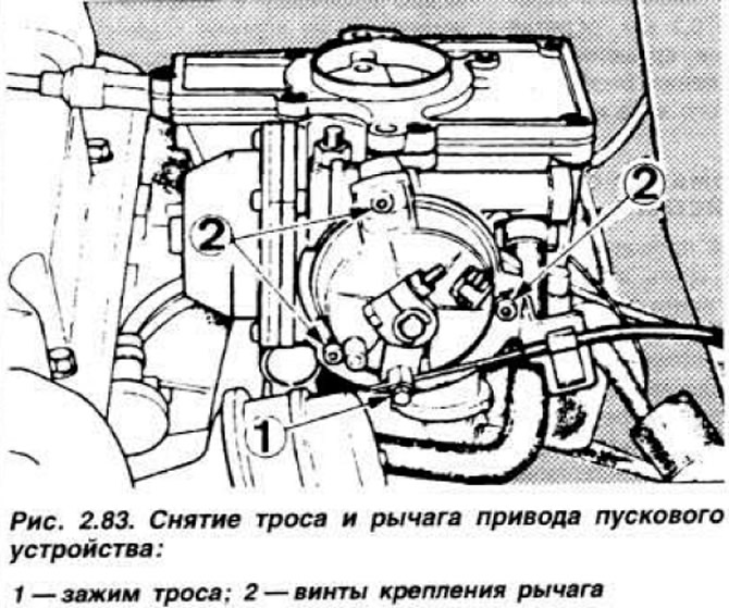
Loosen the three screws and remove the starter. Install a new gasket and secure the starter to the carburetor body. Set the starter drive to the middle position and secure the lever housing. Connect the cable and adjust it as described below, tighten the clamping screw.
Choke Cable Adjustment
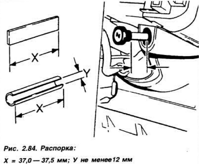
From a steel strip or a piece of pipe with a diameter of at least 12 mm, make a spacer with a length of 37.0-37.5 mm (pic. 2.84).
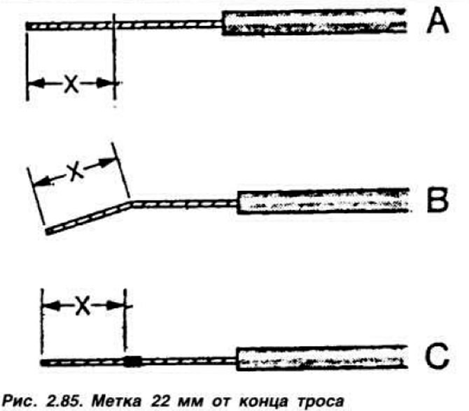
Pull out the choke control knob and install the spacer between the handle and the instrument panel, press the knob to fix the spacer. Using a pencil or tape, mark 22 mm from the end of the cable (on some vehicles, the cable is bent or has a slight thickening in this place) (pic. 2.85).
Insert the cable into the starter clamp and tighten it with a screw against the mark. Pull on the cable sheath. so that the starter drive lever touches the stop 4 (pic. 2.86).
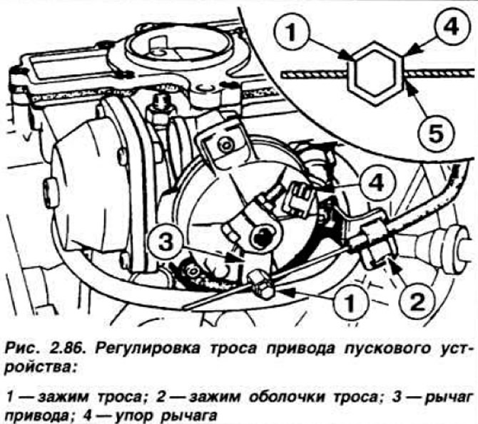
Tighten the sheath clamp screw 2. Remove the spacer and check the position of the trigger drive lever with the handle fully extended and fully recessed. In case of difficulty starting the engine (cold or hot) check the position of the drive lever, which should be included in the lever of the starter cover, check also the position of the spring tab.
Throttle cable adjustment
Disconnect the negative cable from the battery and remove the air filter. Press the accelerator pedal all the way down and block it in this position with a wooden block. Loosen the clamp of the cable sheath so. so that the throttle actuator is in the fully open position. Release the accelerator pedal. again press it all the way down and make sure that the throttle is fully open. Repeat the adjustment if necessary. Install the air filter and connect the battery.
Visitor comments