Removal
The process of removing the cylinder head together with the manifolds is given.
On engines with fuel injection, depressurize the fuel system.
Remove the ground cable from the battery.
Remove the cylinder head cover.
On fuel injected engines, remove the air intake pipes from the throttle body and air cleaner.
Drain the coolant from the cooling system.
Disconnect the hoses from the thermostat housing.
Disconnect the heater coolant hoses from the exhaust manifold and CFI unit.
Disconnect the accelerator cable from the throttle body.
Disconnect the wires from the radiator fan temperature sensor, the coolant temperature sensor (under the intake manifold), and the control valve on the carburetor.
Disconnect the remaining multi-pin wiring connectors from the sensors in the intake manifold and from the oxygen sensor in the exhaust manifold or tailpipe.
On Endura-E engines, disconnect the wiring harness retaining clips and remove the four multi-pin fuel injector connectors.
On vehicles equipped with an air distribution system, remove the air duct and air filter.
Raise the front of the vehicle and support it on stands.
Remove the nuts and bolts and disconnect the exhaust pipe from the manifold. Remove the flange seal. Tie the exhaust pipe to the body with soft wire and lower the car.
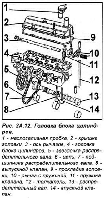
Remove the four mounting bolts and remove the valve train from the cylinder head. Lift the tappets. Arrange them in the order of assembly, marking them from 1 to 8.
Gradually and consistently unscrew the head bolts in the reverse order of tightening. After loosening all the bolts, remove the bolts, then lift the cylinder head and remove the gasket. Only a new gasket should be used. The head bolts can only be used twice, if it is not known how many times the bolts have been used, they must be replaced.
Preparing the head for installation
The mating surfaces of the cylinder head and block must be completely clean. Use a hard plastic or wooden scraper to clean them. Be careful when cleaning, as the aluminum alloy is very easy to damage. Check that carbon deposits have not entered the oil and water passages, this is especially important for the lubrication system, as carbon deposits can block the supply of oil to engine components. Clean the passages if necessary.
Check the mating surfaces of the cylinder head and block for nicks, deep scratches and other damage. If the defects are small, they can be removed by mechanical treatment, but if the defects are significant, the parts must be replaced.
Using a metal ruler and feeler gauge, check the flatness of the mating surfaces.
Clean the bolt holes in the block. Driving a bolt into an oil filled hole can cause the block to burst due to hydraulic pressure.
Installation
Check that the new cylinder head gasket is the same type as the original and that the "TOP" (or "OBEN") marking is facing upwards. Position the new cylinder head gasket on the cylinder block surface on the guide pins. Check that the holes are correctly aligned with the cooling and lubrication system passages (see Fig. 2A.13).

Install the head onto the cylinder block, then insert the bolts and tighten them by hand.
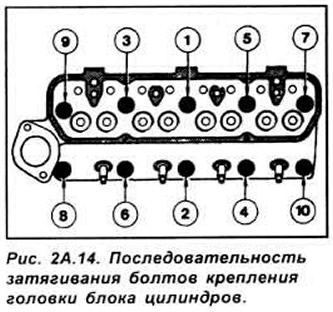
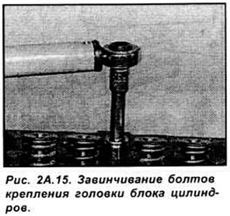
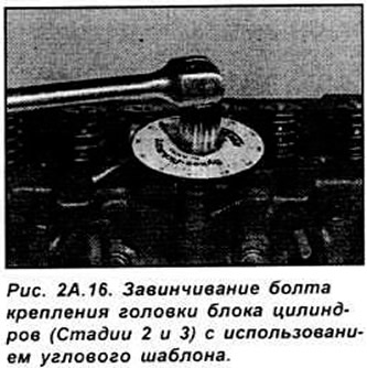
Tightening of the cylinder head mounting bolts is performed in three stages, in a specific sequence (see Fig. 2A.14 - 2A.16)
Lubricate the tappets with clean engine oil, and then insert them into their places in the engine. Install the rocker shaft assembly and secure it with bolts. Adjust the valve clearances. Install the head cover. Perform further operations to install the cylinder head in the reverse order of removal.
Finally, fill with coolant and engine oil.