Withdrawal (models up to 1996)
Remove the instrument cluster.
Printed circuit board
Remove all instrument cluster lights at the rear of the instrument cluster (see fig. 12.55).
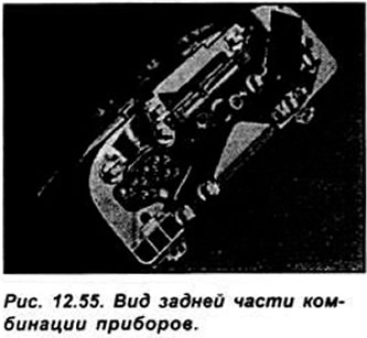
Insert a thin screwdriver from the right into the multi-pin connector holder, loosen the fastening bracket and remove the holder. Carefully remove the PCB from the contacts and pull the PCB back from the instrument cluster.
Speedometer
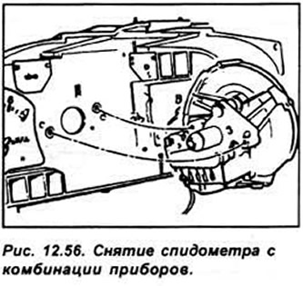
Remove the reset button for the daily counter. Release 4 mounting brackets. unscrew 2 screws and remove the speedometer (see fig. 12.56).
Tachometer
Remove the reset button for the daily counter. Disconnect the mounting brackets and unscrew the mounting screws. Being careful, separate the tachometer from the printed circuit board. Do not place the tachometer face down as silicon fluid may leak out of the tachometer.
Fuel gauge and engine temperature
Remove the reset button for the daily counter. Disconnect the mounting brackets and unscrew the mounting screws.
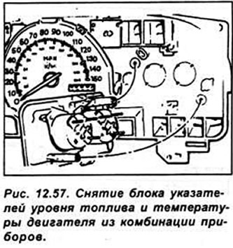
Carefully disconnect the printed circuit board from the sensor clamps. Unscrew the 2 mounting screws and remove the indicator block from the instrument cluster (see fig. 12.57).
Withdrawal (models since 1996)
Remove the instrument cluster. Remove the 2 instrument cluster lights from the top rear of the instrument cluster.
Release the 4 clips and remove the instrument cluster glass.
Tachometer
Unscrew the 2 mounting screws and remove the tachometer.
Fuel gauge and engine temperature
Unscrew the 2 mounting screws and remove the fuel gauge and engine temperature gauge.
Speedometer
Release the clips and remove the speedometer from the instrument cluster.
Printed circuit board
Remove all instrument cluster illumination lamps.
Remove the 2 electrical connector holders from the back of the instrument cluster. Release all contacts from the PCB and remove the PCB
Installation
Installation of the printed circuit board is carried out in the reverse order of removal.
Visitor comments