Egnition lock
Remove the negative terminal from the battery.
Unscrew the 2 screws at the top of the steering column and 4 screws at the bottom and remove the top and bottom casings of the steering column.
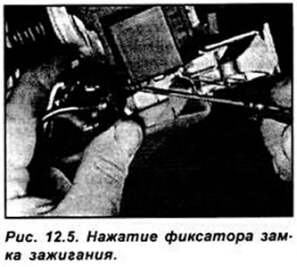
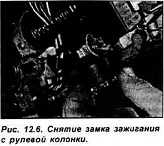
If present, unscrew 1 screw and remove the passive anti-theft system element from the ignition lock socket. Insert the key into the ignition switch and turn it to the "I". Press the ignition lock retainer and remove it from the steering column (see fig. 12.5, 12.6).
Unscrew 6 screws and remove the lower instrument panel from the driver's side. Remove the fuse box and disconnect the ignition switch electrical connector from it. Installation is done in sequence. reverse withdrawal.
Multifunction steering column switch
Remove the steering wheel. Unscrew the 2 upper and 4 lower screws securing the steering column covers and remove them.
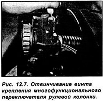
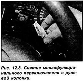
Unscrew the screw and remove the multifunction switch up from the steering column. Disconnect the electrical connector from the switch (see fig. 12.7, 12.8).
Remove the alarm relay from the bottom of the multifunction switch.
Installation is made in sequence, return to removal.
Instrument panel switches
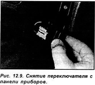
Remove the negative terminal from the battery. Insert a narrow screwdriver between the switch and the instrument panel. When doing this, place a rag or paper under it so as not to damage the surface of the panel. Pull out the switch carefully. In this case, alternately install the screwdriver from above and below. Do not install a screwdriver parallel to the instrument panel, otherwise only the switch cover will be removed.
Disconnect the electrical connector from the switch (see fig. 12.9).
Installation is done in sequence. reverse withdrawal.
Interior door switches
Remove the negative terminal from the battery.
Open the door, unscrew the screw securing the switch and remove it from the door post. Tie a cord to the wires going to the switch.
Disconnect the electrical connector from the switch.
Installation is done in sequence. reverse withdrawal.
Trunk contact platinum
Remove the negative terminal from the battery.
Open the tailgate, unscrew the 2 screws and remove the rear part of the trunk trim.
Using a thin screwdriver, release the mounting brackets and slide the contact plate out of the socket (see fig. 12.10).
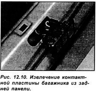
Disconnect the electrical connectors and remove the contact plate.
Installation is made in sequence, return to removal.
Luggage compartment switch contacts
Remove the negative terminal from the battery.
Open the back door and remove the interior trim.
Using a thin screwdriver, remove the switch contacts from the socket (see fig. 12.11).
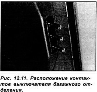
Disconnect the electrical connectors and remove the switch contacts. Installation is done in sequence. reverse withdrawal.
The switch of a control lamp of inclusion of a manual brake (models up to 1996 release)
Remove the negative terminal from the battery.
Remove the front passenger seat and center console.
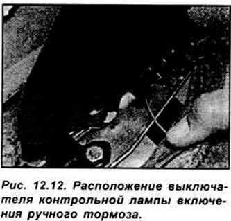
Disconnect the electrical connector from the handbrake indicator light switch, unscrew the 2 screws and remove the switch (see fig. 12.12).
Installation is made in sequence, return to removal.
The switch of a control lamp of inclusion of a manual brake (models from 1996 release)
Remove the negative terminal from the battery.
Using a lever, remove the decorative cover from the handbrake lever.
Disconnect the electrical connector, unscrew the screw and remove the switch from the lever.
Installation is made in sequence, return to removal.
Stoplight switches
Remove the negative terminal from the battery.
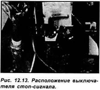
The brake light switch is located in the driver's footwell on the brake pedal bracket (see fig. 12.13).
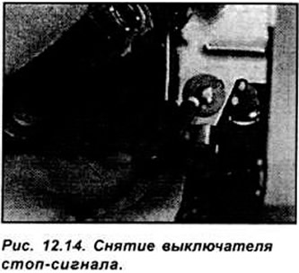
Disconnect the electrical connector from the brake light switch. Turn the switch 90s to the left and remove it from the bracket (see fig. 12.14).
Insert the switch into the hole in the mounting ring. While holding the brake pedal in its original position, slide the switch down until the switch stem contacts the brake pedal. Rotate the switch 40°and lock in this position. Connect the electrical connector and battery and check the operation of the brake light switch. The position of the switch must be such that when the pedal is depressed 5 mm, the brake lights do not light up. At the next 20 mm of pedal travel, the brake lights should light up.
Heater fan switch (models up to 1996)
Remove the negative terminal from the battery. Using the lever, remove the decorative overlay of the heater control panel.
Unscrew the 2 screws securing the heater control panel holder and remove the holder. Unscrew 4 screws and remove the heater control panel. Disconnect the electrical connector from the heater panel light bulb.
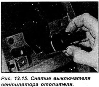
Squeeze the switch mounting brackets. remove it from the panel and disconnect the electrical connector from it (see fig. 12.15).
Installation is made in sequence, return to removal.
Heater fan switch (models since 1996)
Remove the negative terminal from the battery. Unscrew 2 screws and remove the top casing of a steering column.
Unscrew 4 screws and remove the lower casing of a steering column. Remove the steering wheel. Using a lever, remove the decorative panel of the heater control unit.
Unscrew the 2 screws securing the holder to the dashboard and remove the holder. Disconnect the electrical connector from the holder. Squeeze the switch latches, remove the switch from the panel and disconnect the electrical connector from it. Installation is carried out in the reverse order of removal.
Power window switch
Remove the negative terminal from the battery. On pre-1996 models, insert a thin screwdriver between the switch and remote. Remove the switch from the remote. If it cannot be removed from the console, remove the center console and remove the switch from the back of the console.
On models since 1996, use a lever to remove the decorative cover from the base of the gear lever.
Disconnect the electrical connector from the switch and remove the switch.
Installation is made in sequence, return to removal.
Electrical door mirror adjuster
Remove the negative terminal from the battery using a thin screwdriver as a lever to remove the switch from the socket. Disconnect the electrical connector from the switch.
Installation is made in sequence, return to removal.
Starter lock switch (Automatic transmission)
Remove the negative terminal from the battery. The starter interlock switch is located on the gearbox housing and prevents the engine from starting when the gear lever is in any position other than "R" or "N". The switch can be accessed after lifting the front of the vehicle. Disconnect the electrical connector from the switch, unscrew and remove the switch from the gearbox together with the O-ring.
Installation is made in sequence, return to removal. When installing the switch, use a new O-ring. Check that the engine can only be started when the gear lever is in the "R" or "N".
Visitor comments