Removal
One of the reasons for removing the cylinder head may be replacing the gasket. The presence of defects in the gasket is indicated by a loss of engine power, a decrease in the coolant level with a simultaneous increase in the oil level, as well as by the presence of air bubbles in the coolant, which are clearly visible when removing the expansion tank cap with the engine running.
Note: The cylinder head can only be removed when the engine is cold.
Remove the ground cable from the battery. Remove the air cleaner and disconnect the hoses. On fuel-injected engines, remove the air hose from the fuel distributor and throttle body. Remove the fuel lines from the cold start valve and fuel distributor, and the hose from the retarder valve.
Drain the coolant from the cooling system and remove the hoses from the thermostat. Remove the coolant supply hoses to the automatic choke control mechanism of the carburetor.
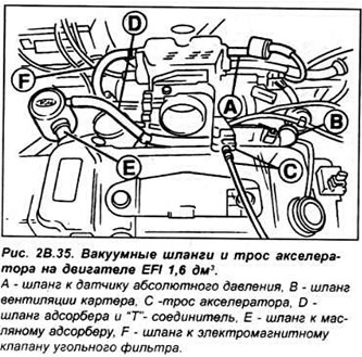
On EFI and SEFI models, disconnect:
- mAP sensor vacuum hose from top of intake manifold (EFI models);
- charcoal canister solenoid vacuum hose from top of intake manifold;
- vacuum hose of the adsorber in a "T"-shaped connector
- brake booster vacuum hose from top of intake manifold;
- coolant hose from the injector intermediate link protrusion and into the thermostat housing (see Fig. 2B.35).
Disconnect the following fuel supply and return hoses:
- on carburetor models, disconnect the fuel supply hose from the pump and the return hose from the carburetor.
- on CFI models, disconnect the fuel return hose from the pump section and at the connector.
- on EFI and SEFI models, disconnect the fuel supply hose from the fuel line. Disconnect the return line from the fuel pressure regulator.
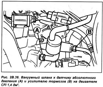
On CFI models, disconnect the brake booster vacuum hose from the intake manifold, the vacuum hose from the MAP sensor, and the charcoal canister (See Fig. 2B.36).
After noting the locations and connections, disconnect the connectors from the following components:
- temperature sensor.
- ignition coils.
- coolant temperature sensor.
- radiator fan thermal switch.
- carburetor.
- grounding of the radio receiver.
- speed sensor.
- fuel injector wiring harness.
- incoming air temperature sensor.
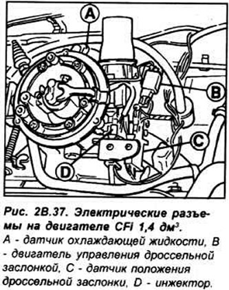
On CFI models, separate the accelerator control motor, throttle position sensor, and injector multi-pin connectors (See Fig. 2B.37).
Remove the high-voltage wires from the spark plugs and unscrew the spark plugs.
Turn the engine crankshaft until the marks on the camshaft pulley and cylinder head, as well as on the crankshaft pulley and oil pump housing, are aligned.
Loosen the two bolts securing the timing belt tension roller and use a screwdriver to move the tension roller away from the belt, compressing the spring, and then tighten the bolts. Remove the timing belt.
Caution: After removing the belt, it is strictly forbidden to turn the crankshaft and camshaft pulleys, as this may cause the pistons to hit the open valves, which will lead to serious damage to the engine.
Raise the front of the car and secure it on stands. Unscrew the exhaust pipe from the exhaust manifold. Unscrew the cylinder head mounting bolts in the reverse order of tightening.
Remove the cylinder head with manifolds. Remove the cylinder head gasket.
Preparing the head for installation
The mating surfaces of the cylinder head and block must be completely clean. Use a hard plastic or wooden scraper to clean them. Be careful when cleaning, as the aluminum alloy is very easy to damage. Check that carbon deposits have not entered the oil and water passages, this is especially important for the lubrication system, as carbon deposits can block the supply of oil to engine components. Clean the passages if necessary.
Check the mating surfaces of the cylinder head and block for nicks, deep scratches and other damage. If the defects are small, they can be removed by mechanical treatment, but if the defects are significant, the parts must be replaced.
Using a metal ruler and feeler gauge, check the flatness of the mating surfaces.
Clean the bolt holes in the block. Driving a bolt into an oil filled hole can cause the block to burst due to hydraulic pressure.
Installation
To prevent the possibility of valve and piston contact, turn the crankshaft so that the piston of the first cylinder is located 20 mm below the TDC position.
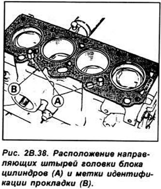
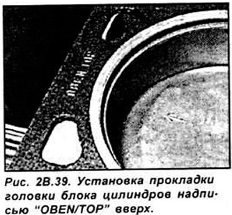
Check that the new cylinder head gasket is the same type as the original and that the "TOP" (or "OBEN") marking is facing upwards. Place the new cylinder head gasket on the cylinder block surface on the pins. Check that the holes are correctly aligned with the cooling and lubrication system passages (see Fig. 2B.39).
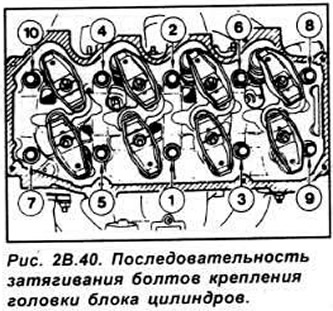
Install the head on the cylinder block, then insert the bolts and tighten them by hand. Tightening the cylinder head mounting bolts is done in four stages, in a specific sequence (see Fig. 2B.40).
Install the camshaft pulley so that the TDC mark indicator is aligned with the mark on the front of the head. Turn the engine with a wrench on the crankshaft pulley until the timing mark on the crankshaft pulley is aligned with the TDC mark (0) on the timing cover.
Install the toothed belt on the camshaft pulley and adjust the belt tension. Further installation is performed in the reverse order of removal. Add coolant and, if necessary, engine oil.