Contents: Models with Ford VV carburetor ↳ Weber 2V Carburetor ↳ Bosch K-Jetronic fuel injection… ↳ Fuel injection system Bosch… ↳ Central fuel injection system ↳ Electronic fuel injection system EFI ↳
Before checking the idle speed and mixture quality, the following checks must be performed.
1. Check the ignition timing.
2. Check the condition and interelectrode gap of the spark plugs.
3. Check that the accelerator cable and, on carburetor models, the choke control cable are adjusted correctly.
4. Check that the crankcase ventilation hoses are not clogged or pinched.
5. Make sure the air filter element is clean.
6. Check that the exhaust system is in good condition.
7. If the engine runs very roughly and unsteadily, check the compression in the engine cylinders.
8. Perform a test drive to warm up the engine to normal operating temperature.
Models with Ford VV carburetor
Location of the idle speed and CO adjustment screws on the Ford VV carburetor
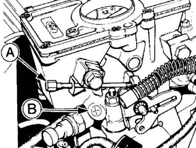
A – idle speed adjustment screw;
B – CO content adjustment screw
Adjusting the idle speed
1. Connect the tachometer to the engine in accordance with the operating instructions.
2. Warm up the engine to normal operating temperature.
3. Disconnect the multi-pin electrical connector of the radiator fan temperature sensor located on the thermostat housing and, using an additional piece of wire, connect the connector contacts, while the radiator fan will operate continuously.
4. On models with automatic transmission, loosen the throttle lever by turning it until there is a gap of 2–3 mm.
5. Check that the air filter is in place and that the vacuum hoses are not pinched, especially between the air filter housing and the carburetor.
6. Increase engine speed to 3000 rpm and hold it for 30 seconds, then let the engine idle. Using a gas analyzer, you will notice that the percentage of CO in the exhaust gases will initially increase, then begin to decrease and stabilize within 5-25 seconds.
7. If necessary, adjust the idle speed with the screw located on the carburetor (see Fig. Location of the idle speed and CO content adjustment screws on the Ford VV carburetor).
Adjusting the quality of the fuel mixture (FM)
Usually, adjustment of the mixture quality is not required, however, if the CO content in the exhaust gases exceeds the permissible limits, adjustment must be made.
1. Using a thin screwdriver blade, remove the plastic plug covering the fuel mixture adjustment screw.
2. Increase engine speed to 3000 rpm and hold it for 30 seconds, then return the engine to idle.
3. Over the next 30 seconds, turn the adjusting screw to adjust the CO content in the exhaust gases (see Fig. Location of the idle speed and CO content adjustment screws on the Ford VV carburetor).
4. If more time is required for adjustment, increase engine speed again to 3000 rpm and hold it for 30 seconds, then return the engine to idle and make further adjustments.
5. Check the idle speed and, if necessary, adjust it, then recheck the CO content.
6. Install the plug on the fuel mixture quality adjustment screw.
7. Remove all used devices, disconnect the additional wire from the connector and connect the connector to the radiator fan temperature sensor.
8. On models with automatic transmission, adjust the downshift lever.
Weber 2V Carburetor
Location of idle speed and CO adjustment screws on Weber 2V carburetor on XR3 and 1.4L models
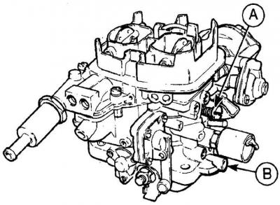
A – idle speed adjustment screw;
B – CO content adjustment screw
Location of idle speed and CO adjustment screws on Weber 2V carburetor on 1.6L models
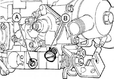
A – idle speed adjustment screw;
B – CO content adjustment screw
Location of idle speed and CO adjustment screws on Weber 2V TLDM carburetor on 1.1 and 1.3 L HCS models
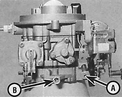
A – idle speed adjustment screw;
B – CO content adjustment screw
Adjustments are made in the same way as on the Ford VV carburetor, but keep in mind that the adjusting screws are located differently.
Bosch K-Jetronic fuel injection system
Location of the idle speed adjustment screw on the throttle body on early Bosch K-Jetronic fuel injection systems
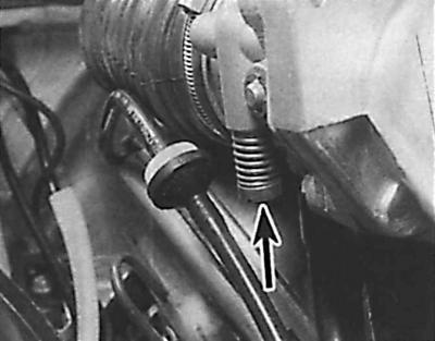
On early models, the idle speed adjustment screw (arrowed) is located at the bottom rear of the throttle body and access to the screw is limited.
Location of idle speed adjustment screw on throttle body on late Bosch K-Jetronic fuel injection systems
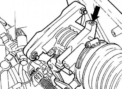
On later models, the idle speed adjustment screw (indicated by the arrow) is located on the top of the throttle body under the plug.
Attention! Adjustment of idle speed and mixture quality should be made only after installation of new components.
1. Connect the tachometer to the engine in accordance with the operating instructions.
2. Warm up the engine to normal operating temperature.
3. Increase engine speed to 3000 rpm and hold it for 30 seconds, then return the engine to idle. Adjust idle speed if necessary.
4. To check and adjust the CO content in the exhaust gases, it is necessary to use a gas analyzer and a 3 mm Allen key.
5. Check idle speed.
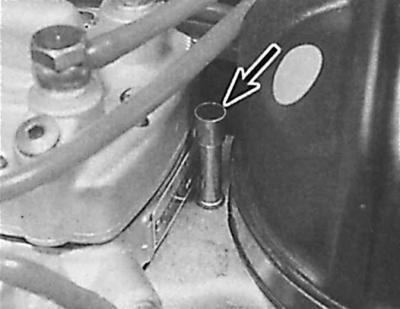
6. Remove the plug (indicated by the arrow) from the top of the fuel mixture adjustment screw tube on the fuel distributor.
7. Check and, if necessary, adjust the CO content in the exhaust gases by turning the adjusting screw with an Allen key. If necessary, adjust the idle speed.
8. If more time is required for adjustment, increase engine speed again to 3000 rpm and hold it for 30 seconds, then return the engine to idle and make further adjustments.
9. Install the plug on the adjusting screw, disconnect the gas analyzer and tachometer.
Fuel injection system Bosch KE-Jetronic
Location of the idle speed adjustment screw on the throttle body on Bosch KE-Jetronic fuel injection systems
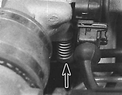
On later models, the idle speed adjustment screw (indicated by the arrow) is located on the side of the throttle body.
Attention! Adjustment of idle speed and mixture quality should be made only after installation of new components.
1. Connect the tachometer to the engine in accordance with the operating instructions.
2. Warm up the engine to normal operating temperature.
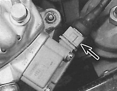
3. Disconnect the multi-pin electrical connector (indicated by the arrow) in the pressure drive located on the side of the fuel distributor.
4. Increase engine speed to 3000 rpm and hold it for 30 seconds, then return the engine to idle. Adjust idle speed if necessary.
5. To check and adjust the CO content in the exhaust gases, it is necessary to use a gas analyzer and a 3 mm Allen key.
6. Check idle speed.
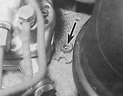
7. Unscrew the plug (indicated by the arrow) from the top of the fuel mixture quality adjustment screw tube on the fuel distributor.
8. Check and, if necessary, adjust the CO content in the exhaust gases by turning the adjusting screw with an Allen key. If necessary, adjust the idle speed; in doing so, remove the Allen key, as this may damage the fuel distributor.
9. If more time is required for adjustment, increase engine speed again to 3000 rpm and hold it for 30 seconds, then return the engine to idle and make further adjustments.
10. Screw the plug onto the adjusting screw, disconnect the gas analyzer and tachometer.
Central fuel injection system
Idle speed and CO content in exhaust gases are regulated by the control unit; manual adjustment is not required.
Electronic fuel injection system EFI
Idle speed is regulated by the EES IV control unit; manual adjustment is not provided.
1. To adjust the quality of the fuel mixture, warm up the engine to operating temperature.
2. Connect the gas analyzer and tachometer according to the instructions.
3. Increase engine speed to 3000 rpm and hold it for 15 seconds, then return the engine to idle.
4. After the instrument readings have stabilized, check the idle speed and the CO content in the exhaust gases.
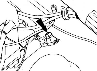
5. To adjust the CO content in the exhaust gases, remove the plug from the adjustment potentiometer located on the wing panel behind the left pillar support (indicated by the arrow) and, by turning the potentiometer screw, set the required CO content at the corresponding idle speed.
6. If more time is required for adjustment, increase engine speed again to 3000 rpm and hold it for 30 seconds, then return the engine to idle and make further adjustments.
7. Install a new plug on the adjustment potentiometer, disconnect the gas analyzer and tachometer.
The text is available on the specified website info portal: www.fordbook.ru