Fuel burner
The fuel injector, centrally located in the CFI assembly, is a solenoid valve that delivers a specific dose of fuel for the appropriate engine load condition. This dose of fuel in the form of finely atomized particles is sent directly to the intake manifold. At idle, the fuel injector opens on every second intake stroke, while the vehicle is moving, on every intake stroke. In this case, the nozzle is under constant fuel pressure, which is provided by the fuel pump and maintained by the pressure regulator.
Depressurize the fuel system and equalize the pressure in the tank to atmospheric pressure by removing the fuel filler neck.
Remove the negative terminal from the battery. Remove the air filter housing.
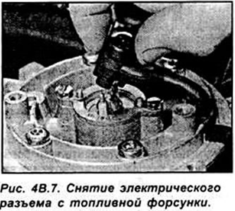
Remove the electrical connector from the top of the fuel injector (see fig. 4B.7).
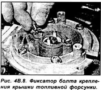
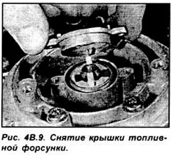
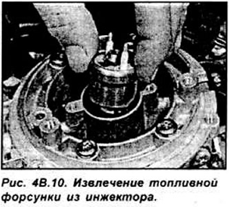
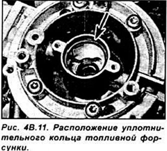
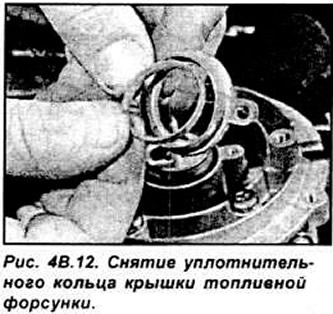
Bend the clamps and unscrew the fuel injector mounting bolts Remove the fuel injector mounting cover and, noting its location, remove it from the injector (see fig. 4B.8-4B.12).
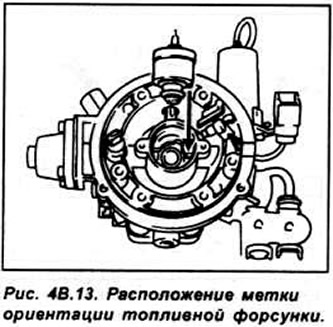
Installation is made in sequence, return to removal. When installing the fuel injector, it is necessary to use new o-rings, which must be lubricated with clean engine oil before installation (see fig. 4B.13, 4B.14).
Fuel pressure control
The fuel pressure regulator is installed directly in the injector housing. It controls the fuel pressure and maintains its value at the fuel injector, equal to 1 bar. Excess fuel is returned to the fuel tank. The pressure regulator has a mechanical principle of operation with a spring-loaded diaphragm. Remove the injector from the engine.
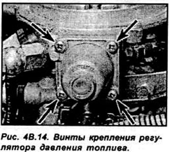
Unscrew the 4 screws securing the regulator and remove it. marking the position in which it was installed. Do not remove the plug located in the outer center of the regulator and do not adjust with the screw. located under the plug, because this will change the pressure in the fuel system.
Disassemble the regulator if necessary. while noting the location of the parts, and check them for wear and damage. Assemble the regulator by installing the small spring, valve, diaphragm, large spring, cup and regulator cap in series. Insert the regulator into the injector and secure it with screws.
If the central adjustment screw of the regulator has been rotated, make the initial adjustment by screwing the screw in by hand and backing out 3 full turns. Install the injector on the engine. If the central pressure adjustment screw on the regulator rotated, then at the first opportunity it is necessary to check the pressure in the fuel system at the service station.
Injector
Relieve the pressure in the fuel system. Remove the negative terminal from the battery.
Remove the air filter housing. Pinch the coolant supply hoses to the injector and disconnect them from it.
Disconnect the supply and return fuel pipes from the injector. Remove the accelerator cable from the injector.
Disconnect the intake air temperature sensor and throttle control motor. Disconnect the vacuum hose from the injector.
Unscrew the 4 screws and remove the injector from the intake manifold Remove the injector gasket (see Figure 4B.15).

Clear interfaced surfaces of an injector and an inlet collector Installation is made in sequence. reverse withdrawal. Check and, if necessary, add coolant to the cooling system. After installing the injector, turn on the ignition at least 5 times in order to increase the pressure in the fuel system and check its tightness.
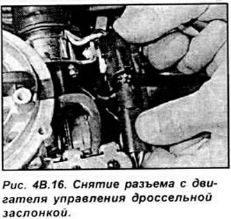
Throttle control motor
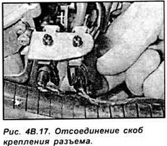
Remove the negative terminal from the battery. Remove the air filter housing Disconnect the electrical connectors from the throttle position sensor and throttle control motor (see fig. 4V 16, 4V.17).
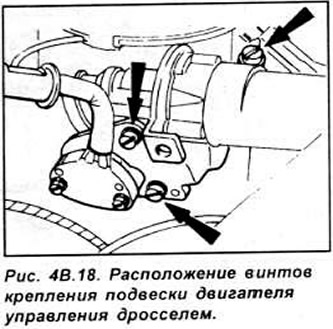
Unscrew the suspension mounting screws and remove the suspension from the throttle control motor (see figure 4B.18).
Unscrew the screws securing the engine to the suspension and remove it from the suspension Installation is performed in the reverse order of removal.
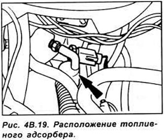
Fuel adsorber
The fuel canister is attached to the intake manifold absolute pressure sensor (see fig. 4B.19).
Remove the negative terminal from the battery. Disconnect the vacuum hoses from the fuel canister and remove it.
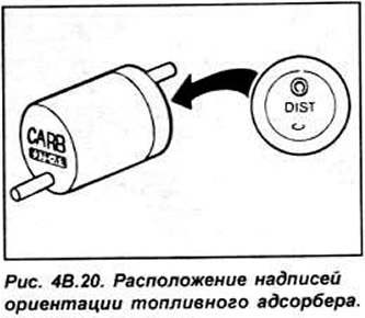
Installation is done in sequence. reverse of removal Position the fuel canister with the mark "CARB" to the intake manifold and label "DIST to absolute pressure sensor (see fig. 4B.20)
ECU
Remove the negative terminal from the battery
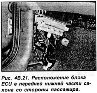
Remove the trim from the front lower part on the passenger side. To do this, turn the fastening knuckle with a screwdriver a quarter of a turn and disconnect the trim (see fig. 4V.21).
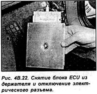
Release the ECU from the holder, then unscrew the mounting bolts and remove the electrical connector (see fig. 4B.22).
Installation is made in sequence, return to removal.
Intake air temperature sensor
Remove the air filter housing. Remove the connector from the sensor, then unscrew the sensor from the injector.
Installation is carried out in the reverse order of removal
Throttle position sensor
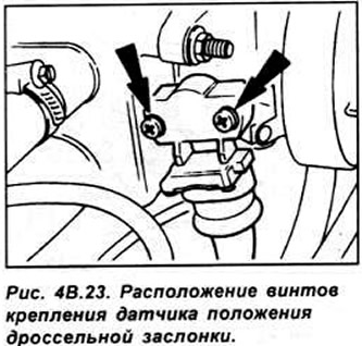
Remove the air filter housing. Remove the electrical connector from the sensor. Unscrew the screws and remove the throttle position sensor housing. Do not rotate the sensor in the removed position, as it is very easy to damage it (see Figure 4B.23).
Installation is made in sequence, return to removal. At the same time, exactly align the cut on the throttle valve axis with the protrusion on the sensor. Tighten the sensor mounting screws evenly (see fig. 4B.24).

Vehicle speed sensor
The speed sensor is mounted on the speedometer drive shaft. It creates an alternating voltage, the frequency of which is proportional to the speed of the car.
The sensor is installed at the base of the speedometer motor drive and is removed from its drive gear.
Absolute pressure sensor
The sensor is located on the right side of the rear of the engine compartment (see fig. 4B.25).
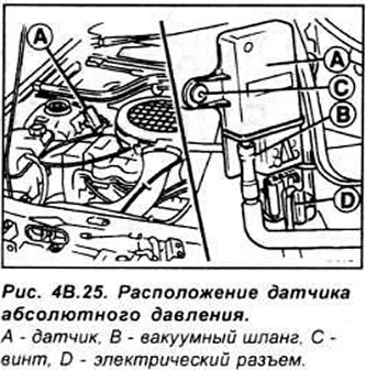
Disconnect the electrical connector and vacuum hose from the sensor. Unscrew the 2 fixing screws and remove the sensor. Installation is carried out in the reverse order of removal.
Power steering pressure sensor.
Remove the electrical connector from the sensor. Unscrew the sensor. Place a clean rag under the transducer to catch any escaping fluid. Check the condition of the sensor O-ring and replace it if necessary (see fig. 4B.26).
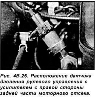
Installation is made in sequence, return to removal. Top up the fluid level in the steering system if necessary.
Oxygen sensor
The oxygen sensor is mounted on the front exhaust pipe and is electrically heated to reach operating temperature after a cold start. The voltage signal that occurs in the sensor when the oxygen content changes is used by the ECU together with the signal parameters from other sensors to prepare the optimal fuel mixture.
Remove the electrical connector from the sensor wire. Raise the front of the car and secure it on stands. Unscrew the sensor from the front exhaust pipe and remove it from below the vehicle.
Installation is made in sequence, return to removal. Lubricate the threaded part of the sensor with a non-stick compound.
Visitor comments