General view of the CFI fuel injection system
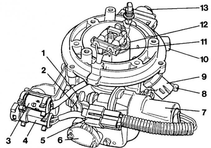
1 - idle adjustment screw; 2 - throttle lever; 3 - nozzle connector; 4 - a connector for throttle sensors; 5 – control connector; 6 - throttle sensor; 7 - control of the executive engine; 8 – connection of a vacuum hose; 9 - intake air temperature sensor; 10 – connection of the fuel pump; 11 – a socket of inclusion of the valve of injection; 12 - injection valve; 13 - fuel pressure regulator
Functional diagram of the CFI fuel injection system
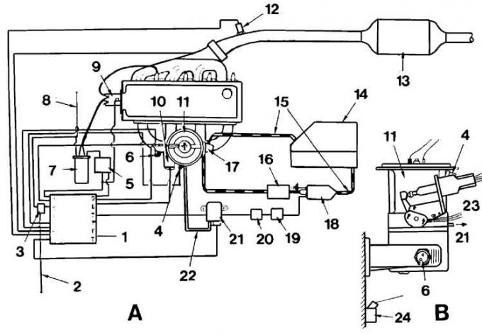
A - general view; B - side view; 1 - control unit; 2 - power flow; 3 - power relay; 4 - intake air temperature sensor; 5 – TFI module; 6 - coolant temperature sensor; 7 - ignition coil; 8 - ignition voltage; 9 - ignition distributor; 10 - executive engine; 11 - CFI device; 12 - lambda probe; 13 - catalyst; 14 – fuel tank; 15 - fuel supply and return pipelines; 16 - fuel filter; 17 - pressure regulator; 18 - fuel pump; 19 - protection sensor; 20 - fuel pump relay; 21 - vacuum sensor; 22 - vacuum tubes; 23 - throttle position sensor; 24 - knock sensor
CFI fuel injection system with intake pipe removed
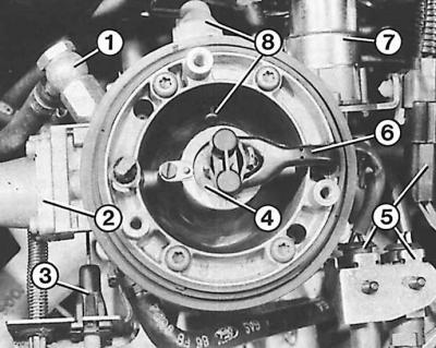
1 - fuel supply; 2 - pressure regulator; 3 - accelerator cable; 4 - nozzle; 5 - connectors; 6 - nozzle mount; 7 - control of the executive engine; 8 - intake air temperature sensor
The CFI fuel injection system receives parameters for fuel mixture preparation through the EEC-IV signal processing module, which processes signals corresponding to air flow, fuel consumption, ignition pulses, coolant temperature, vehicle speed, intake manifold vacuum and lambda probe signal.
Visitor comments