Contents: Assembling the primary shaft ↳ Secondary shaft assembly ↳ Assembly of the differential box ↳ Gearbox assembly ↳
Assembling the primary shaft
1. The installation of bearings on the primary shaft must be carried out using a sleeve of the appropriate diameter, which must rest against the inner ring of the bearing when pressed in.
Caution: When installing a larger bearing, the groove for the retaining ring must be located at the end of the shaft.
Secondary shaft assembly
2. Before assembling the secondary shaft, lubricate all parts with oil used for gearboxes.
3. Secure the secondary shaft vertically in a vice with soft metal pads on the jaws. Position the shaft with the differential pinion facing down.
4. Install on shaft:
- 1st gear pinion, synchronizer locking ring in the direction opposite to the main gear drive pinion, and the retaining ring;
- 1st and 2nd gear synchronizer assembly, with the gear shift fork groove towards the 1st gear pinion, and a new retaining ring;
- 2nd gear pinion, 2nd gear pinion thrust half rings and retaining ring;
- 3rd gear pinion;
- 3rd and 4th gear synchronizer assembly and new synchronizer retaining ring;
- 4th gear pinion;
- bearing (press in with a mandrel), the groove for the snap ring on the bearing must be facing outward;
- bearing snap ring.
Assembly of the differential box
5. Install the speedometer drive gear.
6. Using a suitable mandrel, install the bearings onto the differential case.
7. Install the satellite axle, satellites and axle retainer.
8. Insert the axle gears into the differential box, install them in their places and secure them with the plugs removed earlier. The diameter of the plugs is 22 mm.
9. Install the driven gear of the main transmission on the differential box, with the chamfer facing the box, and secure it with new bolts, tightening them to a torque of 98–128 Nm.
Gearbox assembly
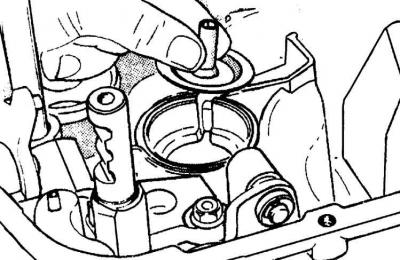
10. Install a new oil deflector and outer bearing ring into the bearing seat of the secondary shaft of the clutch housing.
11. Install the bearing rollers.
12. Calibrate the outer ring of the bearing evenly around the perimeter to ensure precise fixation of the latter.
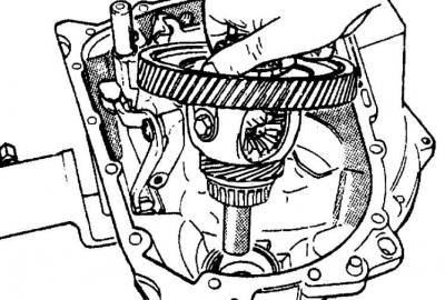
13. Install the differential box with the speedometer drive to the clutch housing.
14. Install the reverse movable gear, with the gear drive located in the groove on the gear hub.
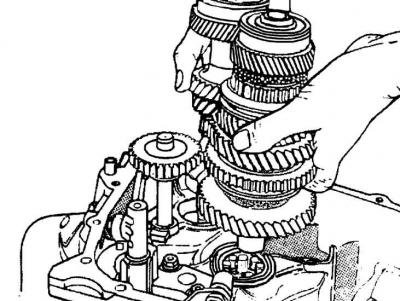
15. Place the primary and secondary shafts together, aligning the gears and installing them as a single block into the crankcase, while moving the movable reverse gear over the 1st gear gear.
16. Install the drive axle spring into the crankcase socket.
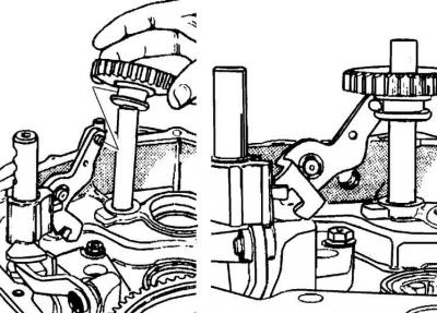
17. Install the locking mechanism and shift forks.
18. Align the fork axle holes and insert the axle with the side with the extended groove into the clutch housing.
19. Check the gear shifting. The gears should shift easily and without sticking. Engage 4th gear, which is necessary to adjust the gear selection mechanism after installing the gearbox on the car.
20. Place the magnet into the socket.
21. Install the outer bearing ring in the gearbox housing, having previously placed two special washers underneath. The washers are installed with their convex sides facing each other, and the larger diameter washer should rest against the outer bearing ring. Calker the outer bearing ring evenly around the perimeter in several places.
22. Install the gasket on the clutch housing and install the gearbox housing. You can use a mallet to seat the gearbox housing.
23. Insert and alternately tighten the bolts connecting the clutch and gearbox housings.
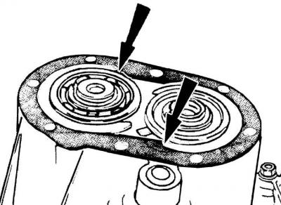
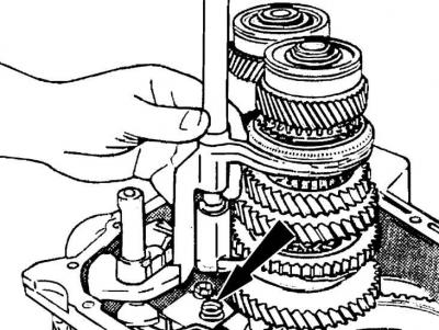
24. Install the retaining rings (indicated by arrows) to secure the bearings, having first selected their thickness so that they fit into the grooves without any gap.
25. To make it easier to install the retaining rings, you can use a screwdriver or other tool to move the shafts upward. Turn the notches on the retaining rings so that they do not overlap with the cover gasket.
26. Install the gasket and cover on the gearbox housing.
27. Install the clutch release shaft, fork and release bearing.