Contents: Disassembling the secondary shaft ↳ Synchronizers ↳ Disassembling the differential box ↳ Checking gearbox parts ↳
Primary shaft of the gearbox
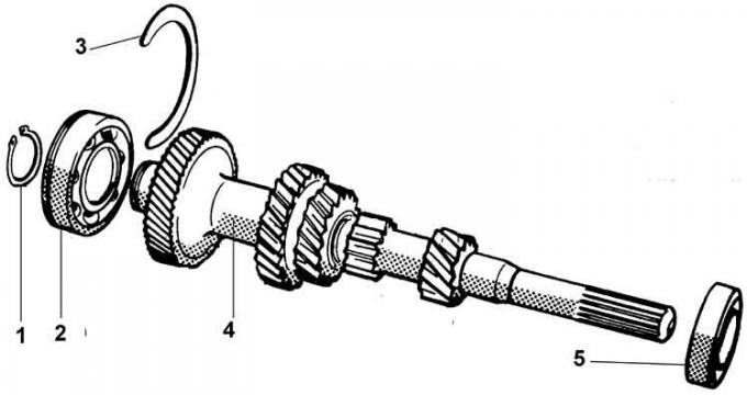
1 – retaining ring; 2 – bearing; 3 – bearing retaining ring; 4 – primary shaft; 5 – bearing
Secondary shaft of the gearbox
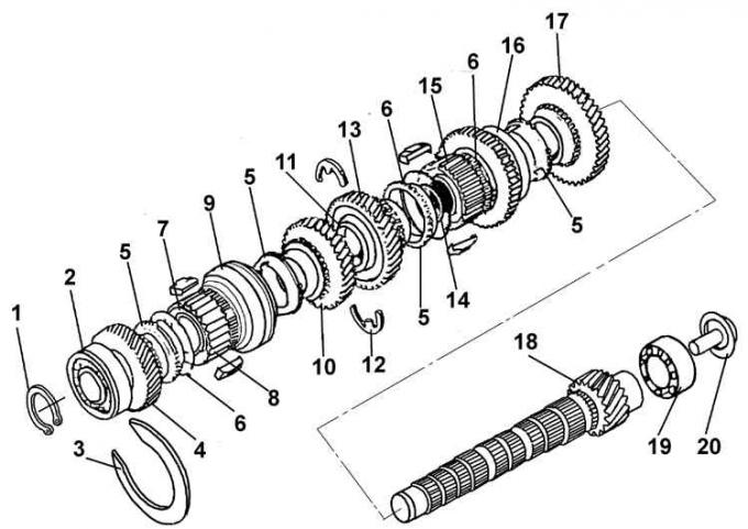
1 – secondary shaft spring retaining ring; 2 – secondary shaft bearing; 3 – bearing retaining ring; 4 – 4th gear pinion; 5 – synchronizer ring; 6 – synchronizer spring; 7 – retaining ring; 8 – hub of synchronizer of 3rd and 4th gear; 9 – sliding ring of synchronizer of 3rd and 4th gear; 10 – 3rd gear pinion; 12 – thrust half rings; 13 – 2nd gear pinion; 14 – retaining ring; 15 – hub of synchronizer of 1st and 2nd gear; 16 – sliding ring of synchronizer 1st and 2nd gear; 17 – 1st gear pinion; 18 – secondary shaft; 19 – secondary shaft bearing; 20 – oil deflector
Synchronizer
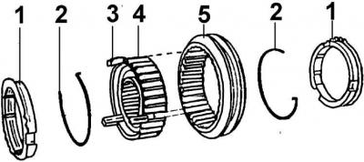
1 – synchronizer locking ring; 2 – spring ring; 3 – cracker; 4 – synchronizer hub; 5 – sliding synchronizer clutch
Differential
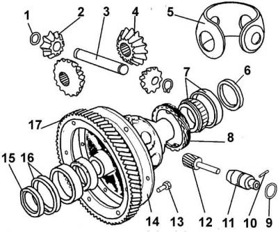
1 – spring retaining ring; 2 – satellite; 3 – satellite axis; 4 – axle gear; 5 – satellite cage; 6, 15 – differential sealing rings; 7 – differential tapered roller bearing; 8 – speedometer drive gear; 9 – circular section gasket; 10 – locking pin; 11 – speedometer drive guide; 12 – speedometer drive gear; 13 – bolt; 14 – differential box; 16 – special convex spring washers; 17 – driven gear of the main transmission
1. Place the gearbox on a suitable assembly table or install it on a workbench on the clutch housing.
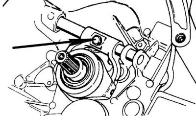
2. Unscrew the lock bolt, remove the clutch release shaft and release bearing.
3. Unscrew the bolts and remove the rear cover from the crankcase.
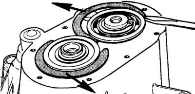
4. Using a screwdriver, remove the retaining rings of the primary and secondary shaft bearings in the directions indicated by the arrows.
5. Unscrew the bolts securing the gearbox housing to the clutch housing and, using light blows from a mallet on the top of the gearbox housing, separate it from the clutch housing and remove it.
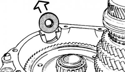
6. Remove the magnet from the socket in the direction indicated by the arrow.
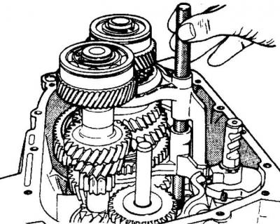
7. Remove the gear shift fork shaft and spring.
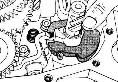
8. Remove the gear shift forks and selector lock.
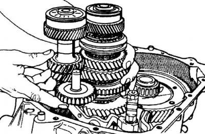
9. At the same time, remove the primary and secondary shafts and the reverse intermediate gear from the crankcase.
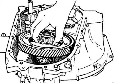
10. Remove the differential box.
11. Remove the secondary shaft bearing from the clutch housing by successively removing the bearing rollers, outer bearing ring and oil deflector using a screwdriver or tweezers.
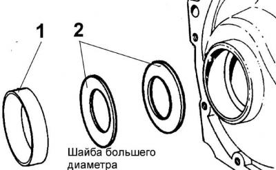
12. Remove the sealing rings and the outer rings of the differential tapered roller bearings from both housings. The outer ring (1) of the gearbox housing bearing rests on two special spring washers (2) with their convex parts facing each other, with the smaller diameter washer located at the bottom of the seat.
Disassembling the primary shaft
13. The primary shaft (see Fig. Primary shaft of the gearbox) is made as a single block of gears, only the bearings can be removed for replacement. To remove the bearings, it is necessary to use a universal puller, preferably with two jaws. When removing the front bearing, the jaws of the puller cling to the end of the outer ring, and when removing the rear bearing - to the annular groove for the retaining ring or to the reinstalled retaining ring of the bearing.
Disassembling the secondary shaft
14. Secure the secondary shaft (see Fig. Secondary shaft of the gearbox) vertically in a vice with soft metal pads on the jaws. The shaft should be positioned with the differential pinion facing down.
15. Remove from shaft:
- bearing snap ring;
- install the outer bearing retaining ring into the outer bearing ring and, using the universal puller jaws to hook onto the retaining ring, remove the bearing.;
- 4th gear pinion;
- synchronizer retaining ring;
- 3rd and 4th gear synchronizer assembly;
- 3rd gear pinion;
- 2nd gear pinion retaining ring and thrust half rings;
- 2nd gear pinion;
- retaining ring and synchronizer 1st and 2nd gear assembly;
- retaining ring and 1st gear.
Synchronizers
16. Remove the springs from both sides of the synchronizer.
17. Remove the synchronizer clutch sliding ring and locking crackers (see fig. Synchronizer).
18. Clean and check the condition of the synchronizer parts.
19. When assembling the synchronizer, ensure that the grooves on the hub and sliding sleeve for the crackers match.
20. Install the springs so that the bent ends of the springs enter the same cracker, but the direction of the bend of the springs should be opposite.
21. If the synchronizer locking rings on the gears become jammed, they must be replaced.
Disassembling the differential box
22. Remove the plugs holding the axle gears and take them out of the differential box (see fig. Differential).
23. Remove the satellite axle lock, remove the axle and satellites.
24. Using a universal puller, remove the bearings from the differential case.
25. Remove the speedometer drive gear.
26. Unscrew the bolts securing the driven gear of the main transmission and, using light taps, remove the gear from the differential box.
Checking gearbox parts
1. Thoroughly clean and visually inspect all gearbox parts.
2. Check the gears for wear and chipped teeth.
3. If the teeth of one of the gears of the primary shaft are worn out, the shaft must be replaced.
4. Check reused rolling bearings for wear and presence of separators.
5. Check the synchronizers and the ends of the gear shift forks for wear, as the forks constantly rub in the grooves of the synchronizer sliding ring.
6. When disassembling synchronizers, it is necessary to note the relative position of the hub and the synchronizer sliding ring.
7. Keep synchronizer rings on the corresponding gears.
8. To clean the connecting surfaces of the clutch housing and gearbox, do not use a hard metal tool that can damage the connecting surface, but use a rag soaked in solvent.
This article is a copy from the website www.fordbook.ru