Caution: The following procedure requires removal of the rear hub to access the brake pads. Please contact Chapter 8 to find out the type of rear axle and determine which axle you are dealing with. A special tool may be required to remove the hub nut (on some types of axles).
Warning: Brake pads should be replaced on both rear wheels at the same time, and never replace new pads on just one wheel, as this will result in uneven braking. Dust generated by brake pad wear may contain asbestos, which is hazardous to health. Never blow out brakes with compressed air or inhale dust. Wear a respirator when working on brakes. Do not use gasoline or petroleum based solvents to clean brakes. Use only brake cleaning fluid or methylated spirits. Do not allow brake fluid, oil or lubricants to come into contact with the brake pads.
1. Remove the rear hubs on both sides as described in Chapter 8, Section 10 or 11.
2. With the rear brake exposed and working on one side at a time, remove dust and dirt from the brake drum, protective cover and brake shoe components. Don't breathe dust - it's dangerous.
3. Inspect the brake drums for excessive wear or signs of damage. The drums should be replaced with new ones (or turned), if there is extensive wear.
4. Check the thickness of the brake shoe linings and if it is below the minimum limit given in the Specifications (or if the surface of the lining is worn down to the level of the rivets), all four rear brake pads need to be replaced with new ones. This replacement is also necessary if the linings are contaminated with oil or brake fluid. In this case, the source of pollution must be eliminated (see Figure 8.4).
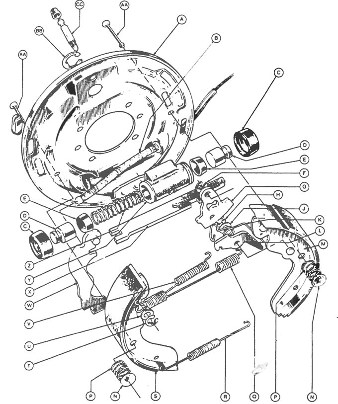
Figure 8.4. Rear brake: A - Protective cover, B - Parking brake cable, C - Protective cap, D - Wheel cylinder piston, E - Piston seal, F - Lock washer, G - Adjusting lever, H - Shoe pillar lock washer, J - Washer, K - Latch spring, L - Adjusting latch, M - Brake shoe, N - Thrust washer, P - Retaining spring, Q - Upper tension spring, R - Lower tension spring, S - Brake shoe lining, T - Lock washer, U - Washer, V - Detent spring, W - Handbrake lever, X - Spacer, Y - Wheel cylinder, Z - Piston spring, AA - Retaining pin, BB - Cylinder lock washer, CC - Removal nipple air.
5. To remove the brake pads, first remove the brake pad retaining spring by pressing on the support washer, turning it 90° and removing the washers, spring and rod from the protective casing.
6. Mark the position of all brake shoe springs, while marking the outside of the shoes to indicate their correct orientation (see Figure 8.6).
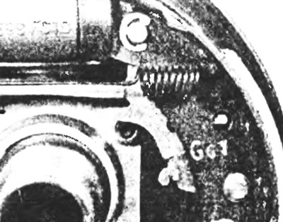
Figure 8.6. Location of the upper tension spring on the shoe.
7. Unhook the lower tension spring from both pads using a pair of pliers (see Figure 8.7).
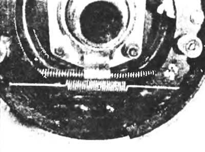
Figure 8.7. Lower tension spring (its fastening).
8. Pull the lower end of the brake shoe away from the stop and unhook the upper tension spring from it. Unhook the other end of the tension spring from the shoe (see figure 8.8).
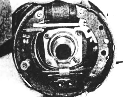
Figure 8.8. Removing the brake pad.
9. Remove the spring from the brake shoe as described in paragraph 5.
10. Pull the upper end of the brake shoe away from the brake cylinder, pull the parking brake cable spring back and disconnect the cable from the parking brake lever. After this, the brake pad can be removed from the protective casing (see Figure 8.10).
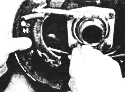
Figure 8.10. Pull the upper end of the brake shoe away from the brake cylinder, pull the parking brake cable spring back and disconnect the cable from the parking brake lever
11. To remove the self-adjusting mechanism from the shoe, remove the two lock washers from the pivot pins. Note the correct position of the setting lever spring (see Figure 8.11).
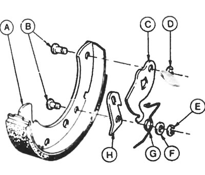
Figure 8.11. Automatic rear brake adjustment mechanism: A - Brake shoe, B - Pins, C - Adjusting lever, D - Lock washer, E - Lock washer, F - Washer, G - Latch spring, H - Adjusting latch.
12. Finally, remove the parking brake lever and spacer from the shoe by pulling the lever back and turning the spacer, then disconnect the spring. Release the pivot pin clamp from its recess, then separate the parking brake lever and washers from the brake shoe (see figure 8.12, a, b, c).
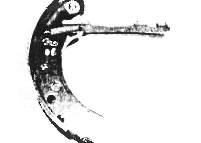
Figure 8.12,a. Brake shoe with parking brake lever - outside view.
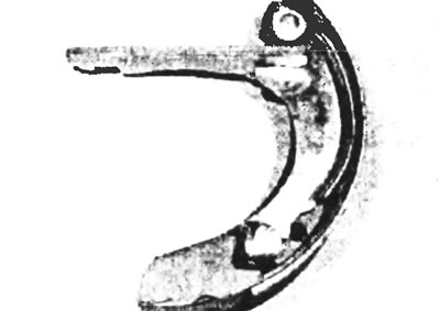
Figure 8.12,b. Brake shoe with parking brake lever - inside view.
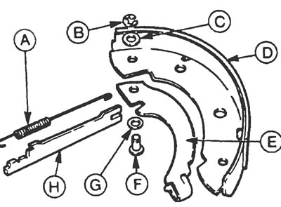
Figure 8.12, c. Brake shoe with parking brake lever (detailed view): A - Locking spring, B - Lock washer, C - Washer, D - Brake shoe, E - Parking brake lever, G - Washer, H - Spacer bar.
13. After removing the brake pads, put a rubber band on the brake cylinder to prevent the pistons from falling out. Be careful not to press the brake pedal while the brake shoes and drums are removed.
14. Completely remove all traces of dust from the pads and protective cover, but do not breathe the dust - it is dangerous to your health.
15. Make sure that the brake cylinder pistons are able to move freely in their sleeves. Inspect the protective caps for damage, and the brake cylinders and brake pipe fittings for brake fluid leaks.
16. Inspect the parking brake components and adjusting mechanism for wear, replacing any worn components with new ones as necessary
17. Installation of the rear brake pads is carried out in the reverse order of removal, but the following additional points should be noted:
- a) When installing brake pads, remember that the primary brake pad has a thicker friction lining;
- b) Apply high temperature brake lubricant to the contact surfaces of the brake shoe on the back plate, being careful not to allow the lubricant to come into contact with the friction linings of the shoe;
- c) Make sure the spacer is installed at the correct angle to the parking brake lever. The adjuster setting lever and latch must be positioned as shown before installing the primary shoe (see figure 8.17,a,b);
- d) Install the rear hubs using the procedures described in Chapter 8;
- d) When finished, press the brake pedal several times to activate the automatic adjustment mechanism;
- e) If necessary, adjust the parking brake as described in Section 14.
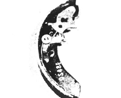
Figure 8.17,a. Location of the self-adjusting mechanism before installing the brake pad - view from the inside.
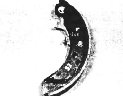
Figure 8.17,b. Location of the self-adjusting mechanism before installing the brake pad - outside view.
[The original can be found on this resource FordBook.ru]