


Warning: Please read the warning before starting work (Section 2) on handling brake fluid and warnings (Section 4) about the dangers of asbestos-containing dust.
Floating caliper
Models with non-ventilated discs
1. Apply the parking brake, loosen the front wheel nuts, jack up the front of the vehicle and support it on supports. Remove the front wheels.
2. Clamp the brake caliper flexible hose with a patented brake hose clamp to reduce brake fluid loss.
3. Wipe clean the area around the banjo connection of the brake hose to the caliper. Using a socket or open-end wrench, loosen and remove the banjo bolt, removing the two copper washers. Cover the banjo joint and the opening in the caliper to prevent dirt from getting inside.
4. Remove the front brake pads (see Section 4).
5. Unscrew the two bolts securing the shoe guide to the steering knuckle and remove the guide. Note that the top bolt cannot be removed completely due to the proximity of the shock absorber, but it can be unscrewed enough to remove the shoe guide (see Figure 5.5).
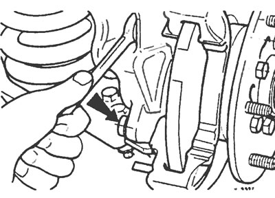
Figure 5.5. Unscrew the two screws (one of which is indicated by the arrow) and remove the caliper pad guide.
6. Installation is carried out in the reverse order of removal. Tighten all retaining bolts to specification and, when complete, remove the clamp from the brake hose and bleed the system as described in Section 2. If the flexible brake hose was pinched as described, it will be sufficient to bleed only the brake circuit on which the work was performed.
Models with ventilated discs
7. Apply the parking brake, loosen the front wheel nuts, jack up the front of the vehicle and support it on supports. Remove the front wheels.
8. Clamp the brake caliper flexible hose with a patented brake hose clamp to reduce brake fluid loss.
9. Wipe clean the area around the banjo connection of the brake hose to the caliper. Using a socket or open-end wrench, loosen and remove the banjo bolt, removing the two copper washers. Cover the banjo joint and the opening in the caliper to prevent dirt from getting inside (see Figure 5.9).
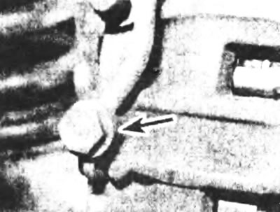
Figure 5.9. Connecting the brake hose banjo connection (indicated by the arrow) to the brake caliper.
10. Remove the front brake pads (see Section 4).
11. Remove the steel cover up the top guide pin bolt and unscrew the bolt. Remove the caliper from the brake pad guide.
12. Unscrew the two bolts securing the caliper pad guide to the steering knuckle. Please note. that the top bolt cannot be removed completely due to the proximity of the shock absorber, but it can be unscrewed enough to remove the shoe guide. Remove the brake shoe guide by lifting it up and then remove the unscrewed bolts (see Figure 5.12).
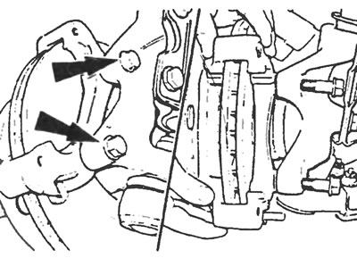
Figure 5.12. Unscrew the two bolts (indicated by arrows), fastening the caliper pad guide to the steering knuckle. Lift the shoe guide up, then remove the bolts.
13. Installation is carried out in the reverse order of removal. Tighten all retaining bolts to specification and, when complete, remove the clamp from the brake hose and bleed the system as described in Section 2. If the flexible hydraulic hose was pinched as described, it will be sufficient to bleed only the brake circuit on which the work was performed.
Fixed support with opposite cylinders
14. Apply the parking brake, loosen the front wheel nuts, jack up the front of the vehicle and place it on supports. Remember that on cars produced before 1992 (with six-stud wheels) the wheel nuts on the left side have left-hand threads and are unscrewed clockwise. Remove the front wheels.
15. Clamp the brake caliper flexible hose with a patented brake hose clamp to reduce brake fluid loss.
16. Wipe clean the area around the brake hose banjo connection to the caliper. Using a socket or open-end wrench, loosen and remove the banjo bolt, removing the two copper washers. Cover the banjo joint and the opening in the caliper to prevent dirt from getting inside.
17. Remove the front brake pads (see Section 4).
18. Unscrew the two bolts securing the caliper to the steering knuckle and remove the caliper (see Figure 5.18).
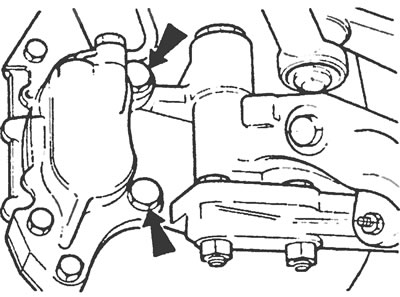
Figure 5.18. Unscrew the two bolts (indicated by arrows); securing the caliper to the steering knuckle and remove the caliper.
19. Install in the reverse order of removal. Tighten all retaining bolts to specification and when finished, remove the clamp from the brake hose and bleed the system (see Section 2). If the flexible hydraulic hose was clamped as described, it will be sufficient to bleed only the brake circuit on which the work was performed.