Caution: To avoid uneven braking, both front brake discs must be resurfaced or reground at the same time.
Inspection
1. Remove the brake pads (see Section 4).
2. Clean all traces of corrosion from the disc. While rotating the disc, inspect it for deep nicks, grooves or cracks. Using a micrometer, measure the thickness of the disc in several places (see Figure 7.2). Minor wear and light nicks are normal, however, if excessive wear occurs, the disc should be removed and either re-sharpened by a specialist or replaced with a new one. If re-sharpened, the minimum disc thickness must not be violated. If the disc has cracks, it must be replaced with a new one without any options.
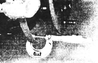
Figure 7.2. Using a micrometer to measure disc thickness.
3. You should also check the disc runout, but first the front hub bearings should be checked and, if necessary, adjusted (see chapter 10). It is better to check the runout with a dial indicator, although measuring the gap between the disc face and a fixed point with a feeler gauge can also give a satisfactory result. You should check both sides of the disc in the middle of the contact surface of the brake pad. Rotate the disk, noting the difference between the measurements as the disk rotates (see Figure 7.3). The difference between the minimum and maximum recorded dimensions will give the disc runout.
4. If the runout is greater than the specification, check the disc thickness unevenness as follows. Mark eight points around the circumference of the disc at a distance of 45 from each other, then measure the thickness of the disc at these eight points with a micrometer at a distance of 15 mm from the outer edge of the disc. If the difference between the minimum and maximum thickness is greater than that specified in the specification, the disc must be replaced with a new one.
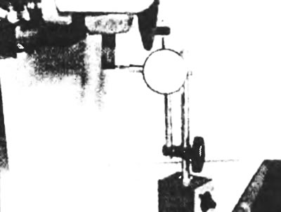
Figure 7.3. Using a dial play indicator with a stand to measure brake disc runout.
Removal
5. Remove the caliper and, where applicable, the pad guide, referring to section 5, but do not disconnect the brake hose. Set aside accordingly (or hang) support so as not to stretch the hose.
6. Turning to Chapter 10, remove the front wheel hub together with the brake disc. If the original disc and hub are to be reassembled, mark them to show their relative positions (see Figure 7.6).
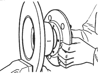
Figure 7.6. If the same disc and hub will be used, mark their relative positions.
7. Using a screwdriver, bend the locking tabs (if installed) and unscrew the bolts securing the disc to the hub in a diagonal sequence.
Installation
8. Install the front brake disc in the reverse order of removal, paying attention to the following additional points:
- a) Before assembly, clean the contact surfaces of the brake disc and hub, then make sure that the marks made during removal are aligned;
- b) Always use new locking tabs when installing (if they are provided) for disc fixing bolts;
- c) Adjust the hub bearings (see Chapter 10).