Examination
1. Check the operation of the booster by pressing the foot brake four or five times with the engine off to release the vacuum. Start the engine with the foot brake still applied. When starting the engine, you should feel a noticeable "recoil" in the brake pedal associated with the vacuum buildup. After letting the engine run for at least two minutes, turn it off. If the brake pedal is now pressed again, a hissing sound from the booster should be heard when the pedal is pressed. After about four or five presses, the hissing noise should stop and the pedal will become more difficult to press.
2. If the amplifier operation deviates from the described mode, inspect all vacuum connections in the amplifier and vacuum pump. Check the vacuum hose and one-way valve. If these tests do not reveal any problems, then the amplifier is faulty and needs to be replaced.
Removal
3. Contact Section 10 and remove the master cylinder.
4. Disconnect the vacuum hose from the booster one-way valve by pulling on it. If it does not come off, help it by levering it, which can be done with a screwdriver if its tip is inserted under the flange of the elbow pipe.
5. In the vehicle cabin, disconnect the booster rod from the brake pedal by removing the spring clip, as well as the pin with a head and a hole for the cotter pin.
6. Disconnect the wiring plug from the brake light switch on the brake pedal bracket, then rotate the switch 90° and remove it from the bracket.
7. After unscrewing the two nuts securing the amplifier to the bulkhead, remove the amplifier (see Figure 12.7.).
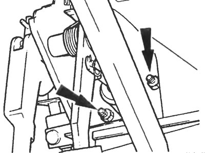
Figure 12.7. Location of the amplifier fixing bolts (indicated by arrows).
8. The amplifier cannot be repaired and therefore must be replaced with a new one in case of failure.
Installation
9. Installation of the vacuum booster is carried out in the reverse order of removal, but the following points must be noted:
- a) Tighten the lock nuts to the specified torque;
- b) Make sure the brake light switch is securely clamped in position and that its wiring is secure;
- c) Contact Section 10 after installing the master cylinder, then top up and bleed the system (Section 2).
[The material was copied from an information website: FordBook.ru]