2. The brake booster cannot be repaired. If problems occur, replace it.
Removal
3. Unscrew the nuts securing the master cylinder to the booster and carefully move the master cylinder forward until the support studs are visible. Be careful not to bend or twist the brake pipes (see picture).
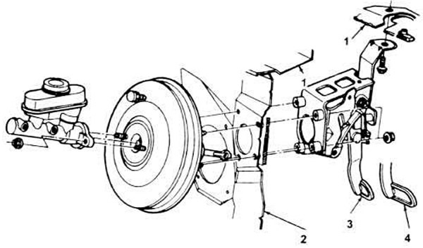
16.3. Brake booster mounting parts.
1. Hood.
2. Instrument panel.
3. Manual transmission.
4. Automatic transmission.
4. Disconnect the vacuum hose where it attaches to the brake booster.
5. Working under the steering column, disconnect the brake light switch electrical connector, then remove the push rod retaining clip and nylon washer from the brake pedal stud. Remove the push rod from the stud (see figure 17.2).
6. Also unscrew the nuts securing the brake booster to the firewall.
7. Carefully disconnect the amplifier from the firewall and remove it from the engine compartment.
Installation
8. Place the booster in place on the firewall and tighten the support nuts. Connect the rod and brake light switch to the brake pedal. Install the retaining clip on the pedal stud.
9. Connect the brake master cylinder to the booster. Tighten the nuts to the specified torque.
10. Check the operation of the brake system thoroughly before driving on the road.
Adjustment
11. Some amplifiers have an adjustable rod. They are connected to the amplifier at the factory and usually do not require adjustment, but if you have any suspicions, you can make a feeler gauge from a sheet of metal (see the picture).
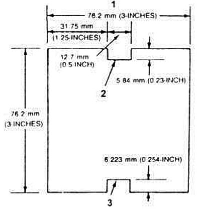
16.11. Brake booster rod template.
1. Dimensions of the feeler gauge.
2. Minimum.
3. Maximum.
12. Some common symptoms of an out of adjustment brake lever include brake vibration (brake lever too long), too much brake pedal travel accompanied by a roaring sound from the booster (brake lever too short).
13. To check the length of the rod, unscrew the master cylinder from the booster and mark it on the side. It is not necessary to disconnect the hydraulic lines, but it is important not to bend them.
14. Block the front wheels, apply the parking brake, and put the gearbox in "park" or "neutral" position.
15. Start the engine and place the feeler gauge against the end of the rod, approximately 2.3 kg (5 lbs) of force must be applied to force the rod into the booster housing (see figure). The length of the rod should be between the minimum and maximum marks on the feeler gauge. If not, adjust its length by holding the knurled part with pliers and turning the end with a wrench.
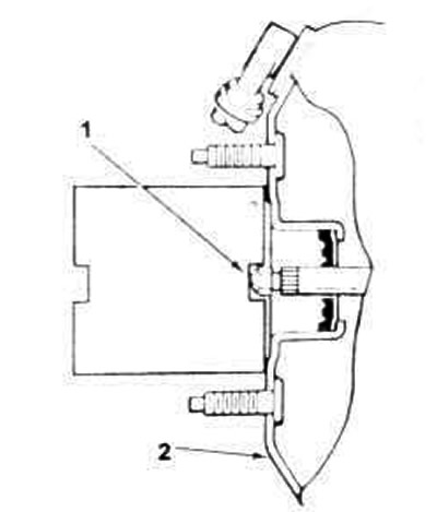
16.15. Checking the length of the rod (the rod is manufactured in factory conditions and most likely will not require adjustment).
1 Adjust the stem screw so that pressure is applied to the feeler gauge (approximately 2.3 kg (5 lbs)).
2. Amplifier housing.
16. After completing the adjustment, reinstall the master cylinder and check the operation of the brakes.
This publication was borrowed from the website: FORDBOOK.RU