Right drive shaft
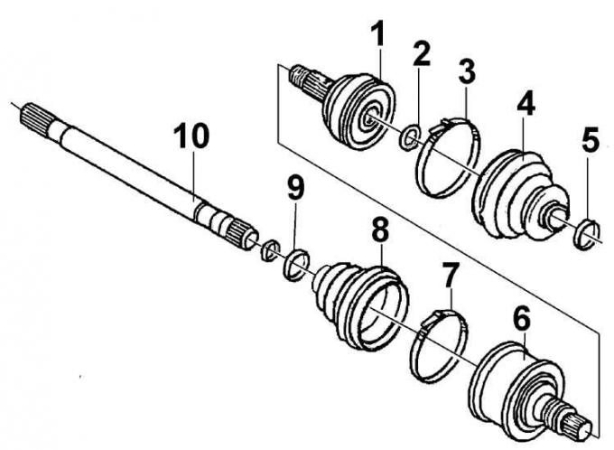
1, 6 – ball joint; 2 – retaining ring; 3, 5, 7, 9 – clamp; 4, 8 – protective cover; 10 – drive shaft
Left drive shaft
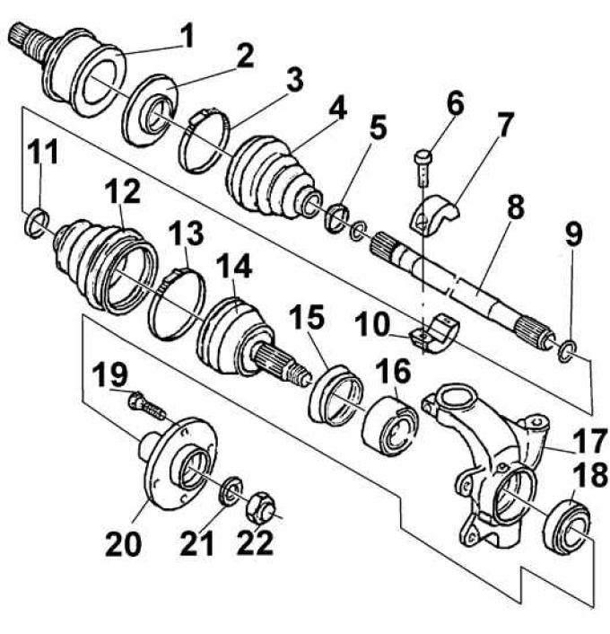
1, 14 – ball joint; 2 – flange; 3, 5, 11, 13 – clamp; 4, 12 – protective cover; 6 – bolt; 7, 10 – vibration damper; 8 – drive shaft; 9 – retaining ring; 15 – sealing ring; 16, 18 – bearing; 17 – steering knuckle; 19 – bolt; 20 – hub; 21 – washer; 22 – hub nut
Outer and inner joints of the drive shaft
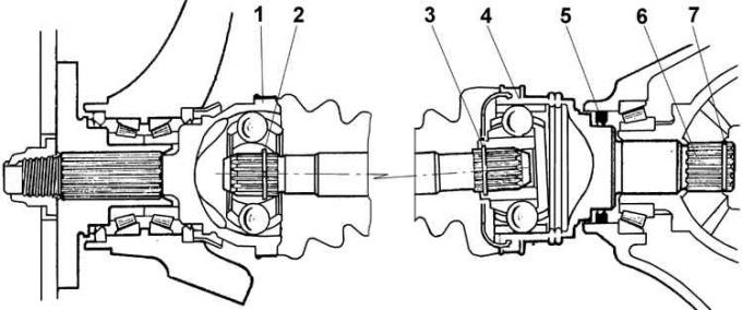
1 – outer hinge; 2 – outer hinge retaining ring; 3 – inner joint retaining ring; 4 – internal hinge; 5 – sealing ring; 6 – splined tip of the inner joint; 7 – shaft retaining ring
Torque is transmitted from the gearbox to the drive wheels via drive shafts of different lengths. The right shaft is longer than the left one, has a larger diameter and has a tubular cross-section. A vibration damper mounted on the right shaft serves to eliminate vibrations. Each shaft consists of three parts: the inner and outer constant velocity joints (CV joints) and the central part of the shaft. The end of the inner joint housing with its splines enters the splines of the differential axle gear and is fixed in it with an expanding spring retaining ring. The splined end of the outer joint housing is inserted into the wheel hub and fixed with a nut. The CV joints are lubricated with consistent grease, which is replaced only when the joint is disassembled.