Caution! The fuel pump is particularly sensitive to dirt and water inclusions in the fuel.
High pressure fuel pump
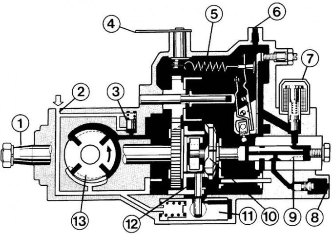
1 – drive shaft; 2 – fuel input; 3 – safety valve; 4 – control lever; 5 – centrifugal regulator; 6 – calibrated fuel return hole; 7 – electromagnetic valve; 8 – fuel outlet to injectors; 9 – piston distributor; 10 – disc cam; 11 – injection advance clutch (conditionally rotated by 90°); 12 – roller; 13 – rotary pump (conditionally rotated by 90°)
Fuel supply to the distribution piston
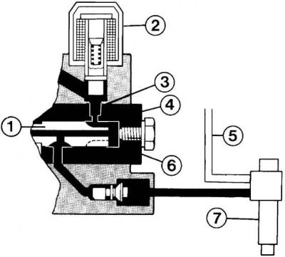
When the distributor piston (1) rotates, the filling hole (3) is positioned under the control spline (4), which is a recess in the distributor piston. Fuel, which is supplied under pressure by the rotary pump, enters the high-pressure chamber (6) in front of the distributor piston and completely fills the chamber; 2 – electromagnetic valve, 5 – fuel return line, 7 – injector.
Fuel injection
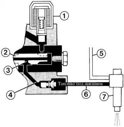
After filling with fuel, the distributor piston (2) continues to rotate and closes the filling hole. In this case, the projections of the disk cam run onto the rollers of the roller ring and the distributor piston begins to compress the fuel. At this moment, the distribution channel (3), with the simultaneous rotation of the piston, is positioned so that it is aligned with the outlet channel (4). Now, through the injection pipeline (8), the fuel is supplied to the nozzle (7) and injected into the cylinder. The remainder of the fuel goes to the fuel tank through the return pipeline (5). The electromagnetic valve (2) must be open, since the fuel goes through it to the distributor piston.
High pressure fuel pump drive
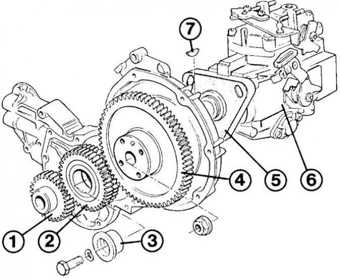
1 – crankshaft drive gear; 2 – intermediate gear; 3 – bearing sleeve; 4 – fuel pump gear; 5 – flange; 6 – high pressure fuel pump; 7 – key