Contents: Exhaust system for treated gases ↳ Exhaust emission control system ↳ Crankcase ventilation system ↳ Fuel Evaporation Control System ↳ Exhaust gas re-burning system ↳ Air pulsation system ↳ Catalyst ↳
Exhaust system for treated gases
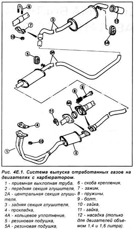
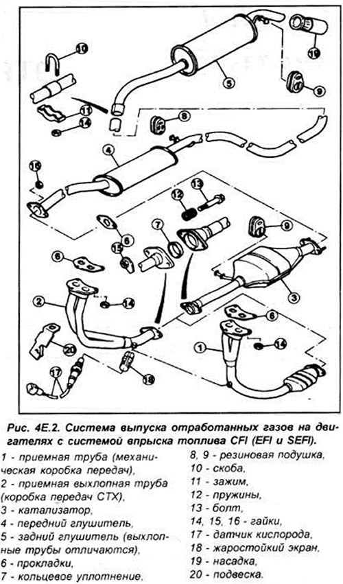
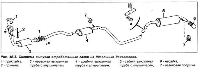
The exhaust system includes an exhaust manifold, a front intake manifold, a catalytic converter and 2 mufflers. The exhaust system consists of three sections: an intake pipe with a catalytic converter, an intermediate pipe and a front muffler, a rear muffler and an exhaust pipe. The system is suspended along its entire length on rubber pads.
Exhaust emission control system
To minimize atmospheric pollution from incompletely burned and evaporated gases and to save fuel, several different systems are used:
- engine management system (fuel and ignition control system);
- crankcase ventilation system (PCV);
- evaporative emission control system (EVAP);
- exhaust gas re-burning (EGR) system;
- pulsating Air System (PAIR);
- catalyst.
Crankcase ventilation system
Some of the combustion products break through the piston rings into the crankcase and if appropriate measures are not taken, they can enter the atmosphere. To prevent this, the crankcase is connected to the air filter by a ventilation hose so that the crankcase gases mix with the fuel-air mixture and are re-burned in the engine cylinders.
On HCS engines, the system consists of a filter in the oil filler cap and a hose connecting the filler cap to the back of the air filter housing. An additional hose connects the air filter to the intake manifold. At idle speed and at low engine loads, crankcase gases are directed to the exhaust manifold without afterburning. Additional air is supplied through 2 small holes located near the valve in the air filter housing, the purpose of which is to prevent the creation of a large vacuum. As the engine load increases, when the vacuum in the intake manifold decreases, the valve opens and crankcase gases are directed through the air filter housing, where they mix with the fuel mixture and are afterburned. The operating principle of the crankcase ventilation system on Endura-E engines is similar to that described.
The CVH and RTE engines use a closed crankcase ventilation system. It is similar to the one described above, except that the crankcase ventilation hose is connected directly to the head cover.
On Zetec and Zetec-E engines the oil separator is mounted on the front side of the cylinder block and a set of valves in a rubber sealing ring are located at the upper end of the separator.
Fuel Evaporation Control System
This system is designed to prevent fuel vapor from escaping into the atmosphere. The fuel tank has an expansion tank and vent tubes that are designed so that no fuel or vapor can escape, even if the car gets very hot. The vent tubes are connected to a canister containing charcoal, which absorbs hydrocarbon vapors. When the engine is stopped, the fuel vapor is collected in the charcoal canister. When the engine is started, fresh air is sucked in through the canister and the vapors are drawn from the canister to the air filter and into the engine, where they are burned.
Exhaust gas re-burning system
This system, installed on Zetec-E engines, reduces the nitrogen oxide content in the exhaust gases. This is achieved by recirculating some of the exhaust gases through the EGR valve to the intake manifold.
The system consists of an EGR valve, an EGR differential pressure sensor, an EGR solenoid valve, an ECU system and various sensors. The ECU is programmed to produce the ideal EGR valve lift for all operating conditions.
Air pulsation system
The system consists of a one-way electromagnetic air pulse valve, hoses and a check valve. The system introduces filtered air directly into the exhaust ports, using the change in exhaust pressure to supply additional air from the filter into the exhaust system when the pressure in it is below atmospheric. The valve only allows gases to pass in one direction and there is no risk of exhaust gases breaking through to the air filter.
The main function of the system is to increase the temperature of the exhaust gases at start-up, which reduces the time for warming up the catalyst.
Catalyst
The catalytic converter stimulates a chemical reaction to convert carbon monoxide and hydrocarbons in the exhaust gases into carbon dioxide and water. The catalytic converter does not require any maintenance, but should be checked periodically for signs of physical damage. The catalytic converter contains a ceramic insert that is very fragile and can break if the catalytic converter is hit or dropped.
The original article can be viewed on the portal FORDBOOK.ru