Contents: Fuel line and injectors ↳ Fuel pressure regulator ↳ Throttle body ↳ ECU Block ↳ Incoming air temperature sensor ↳ Throttle Position Sensor ↳ Vehicle speed sensor ↳ Absolute pressure sensor ↳ Power Steering Pressure Sensor ↳ Oxygen sensor ↳
Fuel line and injectors
Attention: For simplicity and to ensure absolute cleanliness during disassembly, the removal of the fuel line together with the fuel injectors and pressure regulator is described.
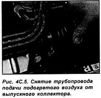
Relieve the pressure in the fuel system and equalize the pressure in the tank with atmospheric pressure by removing the fuel filler cap. Remove the negative terminal from the battery. Loosen the clamps and remove the air hose supplying heated air from the exhaust manifold (see Fig. 4C.5).
Remove the spark plug wires from the spark plugs and move them to the side.
Remove the nuts and bolt and separate the accelerator cable housing from the throttle body. Remove the connector from the throttle position sensor.
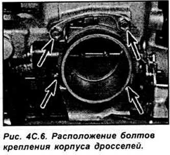
Unscrew the 4 mounting bolts and remove the throttle body and gasket (see Fig. 4C.6).
Disconnect the electrical connectors from the engine temperature sensor and the intake air temperature sensor.
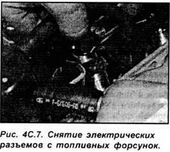
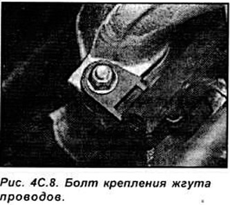
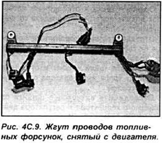
Disconnect the electrical connectors from the fuel injectors, then unscrew the 2 mounting bolts and remove the wiring harness from the fuel line (see Fig. 4C.7-4C.9).
Unscrew the fuel supply line to the fuel line. Close the holes with plugs.
Disconnect the fuel return hose and vacuum lines from the pressure regulator.
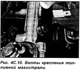
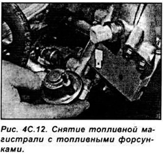
Unscrew the fuel line mounting bolts and remove it together with the fuel injectors (see Fig. 4C.10-4C.12).
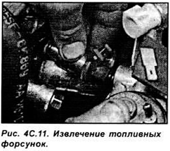
Remove the fuel injectors from the fuel line. Remove the upper and lower O-rings from the fuel injectors. All fuel injector O-rings must be replaced, even if only one injector was replaced.
Before installation, make sure the mating surfaces are clean. Lubricate the new fuel injector O-rings with engine oil.
Installation is performed in the reverse order of removal. When installing the fuel line in place, check that all injectors are correctly positioned.
Start the engine and check the fuel system for leaks.
Fuel pressure regulator
Relieve the pressure in the fuel system and equalize the pressure in the tank with atmospheric pressure by removing the fuel filler neck.
Remove the negative terminal from the battery.
Loosen the clamp and remove the fuel return line from the regulator.
Remove the vacuum tube from the regulator nozzle (see Fig. 4C.13).
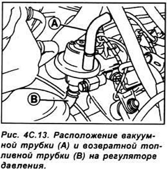
Unscrew 2 bolts and remove the regulator. Remove the old sealing ring.
Installation is performed in the reverse order of removal. Lubricate the new sealing ring with engine oil. After installing the regulator, fuel and vacuum lines, turn on the ignition about 5 times (without starting the engine) and check the tightness of the fuel system.
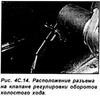
Idle speed control valve. Remove the negative terminal from the battery.
Disconnect the electrical connector from the valve (see Fig. 4C.14).
Unscrew the 4 screws and remove the idle speed control valve. Installation is performed in the reverse order of removal. Start the engine and check its operation. Warm up the engine to operating temperature and check that the idle speed is stable. Turn off the engine, connect the tachometer in accordance with the manufacturer's instructions, restart the engine and check the idle speed, including all electrical consumers. In all cases, the idle speed must meet the technical requirements.
Throttle body
Relieve the pressure in the fuel system and equalize the pressure in the tank with atmospheric pressure by removing the fuel filler neck.
Remove the negative terminal from the battery.
Loosen the clamp and disconnect the heated air supply pipe from the exhaust manifold.
Disconnect the spark plug wires from the spark plugs and move them to the side.
Remove the nuts and bolt and separate the accelerator cable housing from the throttle body. Disconnect the vacuum hoses from the intake manifold and fuel pressure regulator. Remove the electrical connectors from the idle speed control valve, temperature sensor and wire harness connector. Disconnect the fuel return hose from the pressure regulator. Unscrew the throttle mounting bolts and remove the throttle body together with the gasket. Installation is performed in the reverse order of removal.
ECU Block
Remove the negative terminal from the battery.
In the passenger compartment, remove the trim from the front lower part on the passenger side and turn it aside to access the ECU. Release the ECU from the holder, then unscrew the mounting screws and remove the electrical connector. Installation is carried out in the reverse order of removal.
Incoming air temperature sensor
Remove the engine air supply pipes. Disconnect the sensor electrical connector. Unscrew the sensor from the intake manifold.
Installation is carried out in the reverse order of removal.
Throttle Position Sensor
Remove the air supply pipes.
Press the retaining clip and remove the electrical connector from the sensor. Unscrew the screws and remove the sensor from the throttle body. Do not rotate the center part of the sensor in the removed position, as it is very easy to damage it.
Installation is performed in the reverse order of removal. In this case, precisely align the cut on the throttle valve axis with the protrusion on the sensor. Tighten the sensor mounting screws evenly.
Vehicle speed sensor
The sensor is installed at the base of the speedometer drive and is removed from the speedometer drive gear.
Absolute pressure sensor
The sensor is located on the right side of the rear of the engine compartment. Disconnect the electrical connector and vacuum hose from the sensor.
Unscrew the 2 mounting screws and remove the sensor. Installation is performed in the reverse order of removal.
Power Steering Pressure Sensor
Remove the electrical connector from the sensor. Unscrew the sensor. Place a clean rag under the sensor to catch any leaking fluid. Check the condition of the sensor O-ring and replace it if necessary.
Installation is performed in the reverse order of removal. If necessary, bring the fluid level in the steering system up to the norm.
Oxygen sensor
Remove the electrical connector from the sensor wire. Raise the front of the car and secure it on stands. Unscrew the sensor from the exhaust pipe and remove it from underneath the car.
Installation is carried out in the reverse order of removal. Lubricate the threaded part of the sensor with a non-stick compound.