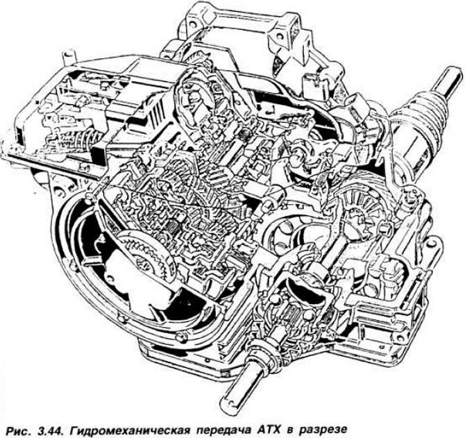
 Fig. 3.42. Hydromechanical gearbox components.
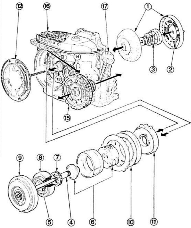
1 - torque converter; 2 — damper; 3 - planetary gear of the torque converter; 4 — turbine shaft; 5 — shaft of the 2nd gear; 6 - planetary gearbox; 7 — freewheel clutch; 8 — direct transmission clutch; 9 — 2nd gear clutch; 10 — reverse clutch; 11 - band brake; 12 - oil pump; 13 - output gear; 14 - intermediate gear; 15 — driven gear of the main transmission; 16 - valve box; 17 — regulator.
From the output gear 13, the torque is transmitted to the driven gear of the main transmission 15 through the intermediate gear 14. The torque converter 1 transmits the engine torque to the gearbox. Under certain conditions, it increases the transmitted torque due to the transformation ratio. In addition, in the II and III gears, it redistributes the transmitted torque to the torque transmitted hydraulically and to the torque transmitted mechanically. The damper 2 dampens vibrations transmitted from the engine to the gearbox when transmitting torque mechanically.
Planetary gear 3 of the torque converter is designed to redistribute torque into torque transmitted hydraulically and torque transmitted mechanically, depending on the vehicle speed.
Shaft 4 of the turbine transmits torque from the torque converter, obtained hydraulically.
Shaft 5 of the 2nd gear transmits torque via the 2nd gear clutch and the crown gear of the planetary gear. Planetary gear 6 ensures forward movement in three gears and reverse movement depending on the position of the clutches and the band brake. Freewheel clutch 7 of the planetary gear transmits torque from the turbine shaft to the crown gear of the 1st gear and reverse gear of the planetary gear (clockwise rotation). Direct gear clutch 8 locks the turbine shaft with the sun gear of the 1st gear and reverse gear of the planetary gear. Second gear clutch 9 locks the shaft of the 2nd gear with the crown gear of the planetary gear in the 2nd and direct (III) gears.
Reverse clutch 10 locks the planetary gear ring gear in reverse.
Band brake 11 locks the drum and the front sun gear in the first and second gears. The brake is actuated by a piston rod, and the piston itself is controlled by oil pressure.
Oil pump 12 continuously supplies oil under pressure for the operation of the hydromechanical transmission, for its lubrication and cooling. The pump begins to operate after the engine is started and is driven by a hexagonal shaft from the torque converter cover.
Output gear 13 transmits torque received from the gearbox to the differential. Intermediate gear 14 and driven gear 15 of the main transmission drive the differential into rotation.
Valve box 16 supplies oil under pressure to the torque converter, band brake, servo drive, clutches and gear shift control regulator.
Regulator 17 controls gear shifting depending on the vehicle speed. It is driven by a worm gear mounted on the differential.
Oil cooler. The oil is cooled in the space between the two radiator pipes of the engine cooling system.
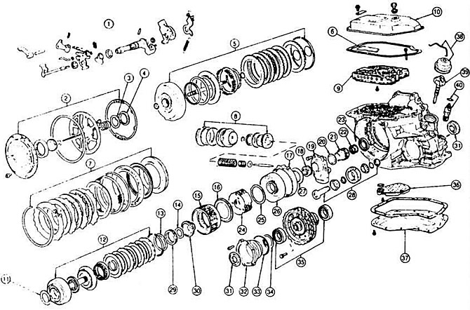 Fig. 3.43. Parts of the hydromechanical gearbox.
1 — selector; 2 - oil pump assembly; 3 - thrust washer No.12; 4 - needle bearing No.11; 5 — clutch 2nd gear assembly; 6 — valve box hatch cover; 7 — reverse clutch assembly; 8 - Band brake servo assembly; 9 - valve box; 10 — valve box cover; 11 - needle bearing No.10; 12 — direct transmission clutch; 13 - thrust washer No.9; 14 - thrust washer No.8; 15 - ring gear; 16 - needle bearing No.7; 17 - band brake; 18 - needle bearing No.6; 19 — output gear cover; 20 - needle bearing No.3; 21 — output gear; 22 - needle bearing No.2; 23 - needle bearing No.1; 24 - driver; 25 - thrust washer No.5; 26 - Front sun gear and drum; 27 - thrust washer No.4; 28 - intermediate gear; 29 — planetary gear freewheel clutch; 30 — sun gear of 1st gear and reverse gear with freewheel clutch cage and direct drive clutch hub; 31 — front wheel drive shaft seals; 32 — differential bearing cage; 33 — bearing race gasket: 34 — adjusting ring; 35 — differential assembly with driven gear and parking brake sector; 36 - oil filter with gasket; 37 — oil pan; 38 - centrifugal regulator cover with clamp and gasket; 39 - centrifugal regulator; 40 — speedometer drive gear with gasket.