Removal
1. After blocking the front wheels, loosen their wheel nuts, then jack up the front of the car and place it on supports. Set the wheels to the straight-ahead position.
2. Remove the cotter pin and unscrew the nut securing the ball joint of the longitudinal steering rod to the steering arm. Using a ball joint puller, release the conical ball joint pin and separate the longitudinal steering rod from the steering arm (see Figure 28.2.).
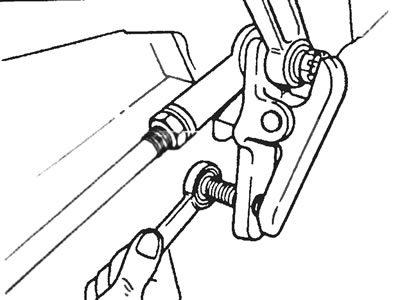
Figure 28.2. Using a ball joint puller, release the ball pin cone and separate the tie rod from the steering knuckle.
3. Unscrew the nut securing the steering arm to the steering gear. If the pitman arm does not have a guide spline, mark the installation position of the pitman arm on the steering shaft by scratching an alignment mark on the face surfaces. Pull the steering arm out of the shaft using a puller (see Figure 28.3).
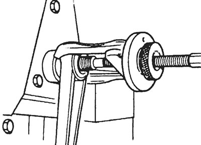
Figure 28.3. Remove the steering arm from the steering shaft using a puller.
4. Unscrew the steering column universal joint pressure plate clamping bolt and move the pressure plate to the side (see Figure 28.4.). Please note that a new bolt will be required when installing the pressure plate.
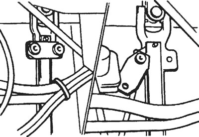
Figure 28.4. Loosen the steering column universal joint pressure plate clamping bolt and move the pressure plate to the side.
5. Unscrew the bolts securing the steering gear to the chassis and remove it (see Figure 28.5).
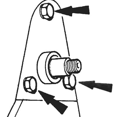
Figure 28.5. Unscrew the bolts securing the steering gear to the chassis (indicated by arrows).
Disassembly
6. Clean the steering gear housing with paraffin and dry it completely.
7. Loosen the lock nut securing the steering arm shaft adjusting screw, then unscrew and remove the three bolts securing the steering arm housing side cover. Remove the side cover, gasket and steering arm shaft (see Figure 28.7).
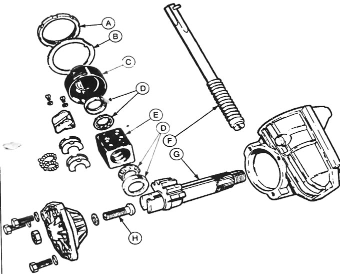
Figure 28.7. Screw-and-nut type steering gear: A - Thrust bearing adjusting lock nut, B - Lock washer, C - Thrust bearing adjusting clamp, D - Thrust bearings, E - Ball nut, F - Steering shaft, G - Steering arm shaft with gear sector, H - Steering arm shaft adjusting screw.
8. Remove the adjusting screw lock nut and unscrew the side cover from the adjusting screw. Remove the adjusting screw and spacer from the steering arm groove (see Figure 28.8).
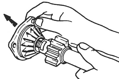
Figure 28.8. Remove the side cover with the adjusting bolt and gasket from the groove in the steering arm shaft.
9. Straighten the tabs of the spring washer securing the thrust bearing adjuster lock nut and unscrew the lock nut with a special wrench (see Figure 28.9.). Remove the spring washer and pull out the steering shaft roll pin.
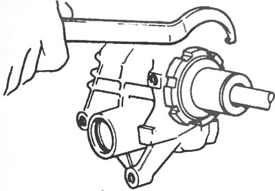
Figure 28.9. Unscrew the adjusting lock nut of the thrust bearing adjusting clamp using a special C-shaped wrench.
10. Remove the thrust bearing adjusting clamp and carefully pull out the steering shaft together with the upper and lower bearings.
11. Using a suitable punch or drift, knock out the outer races of the lower and upper thrust bearings from the steering gear housing and the adjuster, respectively.
12. Clamp the steering nut in a vice with soft pads on the cheeks, unscrew the fixing screws of the guide tube pressure plate and remove the pressure plate (see Figure 28.12).
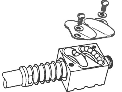
Figure 28.12. After unscrewing the fixing screws, remove the guide tube pressure plate.
13. Remove the guide tubes and take out the 62 steering nut balls. Please note that the steering shaft, steering nut and balls are a set and cannot be purchased separately.
14. Remove the steering gear housing oil seal from the steering arm side.
15. Wash all components thoroughly with paraffin and dry with a lint-free cloth.
16. Inspect all components for damage, cracking, or general excessive wear. Temporarily install the steering knuckle shaft into the steering gear housing bushing and check that there is no excessive clearance between them, then inspect the steering knuckle teeth for wear. Inspect the bearing races and balls for pitting or signs of wear; check if the bushing in the side cover is worn out. Worn bushings can be replaced individually, but if the steering arm shaft and steering shaft need replacing, it will probably be cheaper to purchase a rebuilt steering gear.
17. Purchase new oil seal, side cover gasket and thrust bearing adjuster spring washer.
18. When assembling the steering gear, first insert the oil seal and the outer race of the lower thrust bearing into the steering gear housing, making sure that they are installed straight. Similarly, using a tube of suitable diameter, insert the outer race of the upper thrust bearing into the adjuster.
19. Place the steering nut onto the steering shaft, orienting it correctly, and insert all 62 steel balls, one into each of the four holes. You will have to move the steering shaft a little inside the nut to seat the balls in their grooves, but do this in such a way that the balls do not jump out of the grooves.
20. After installing the guide tubes and aligning their passage holes, install the clamping bar and tighten the fixing screws.
21. After lubricating the thrust bearing races, place them into the outer rings, then install the steering nut and steering shaft into the steering gear housing. Screw the thrust bearing adjuster into the crankcase. Using a suitable torque wrench or pre-load sensor, tighten the regulator so that the correct steering shaft torque specified in the Specifications is achieved.
22. After installing the new lock washer and thrust bearing adjuster lock nut, tighten the lock nut with a special offset wrench. After bending the washer, hook one tongue into the groove of the lock nut and the other into the steering gear housing (see figure 28.22).
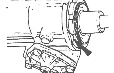
Figure 28.22. Bend one tab of the lock washer (indicated by the arrow) into the groove of the lock nut, and drive the other into the steering gear housing.
23. Insert the adjusting bolt into the steering arm groove, selecting a shim so that the gap between the screw head and the contact surface of the steering arm shaft is 0.05 mm. If necessary, remove the screw, install a new shim, and reinstall the screw.
24. Screw the side cover onto the steering arm shaft adjustment bolt and tighten the lock nut without tightening it completely.
25. Fill the steering gear housing with the appropriate type of grease in the quantity as given in Specifications, then install the new side cover gasket in place.
26. Insert the assembled steering arm shaft with the side cover screwed on into the steering gear housing, ensuring that the central teeth of both shafts and the steering nut are engaged, then tighten the three side cover fixing bolts. Adjusting the steering knuckle shaft preload with the adjusting bolt is performed later, after installing the steering gear on the vehicle.
27. Install the cylindrical pin onto the steering shaft.
Installation
28. Installation of the steering gear is carried out in the reverse order of removal, but please pay attention to the following additional points:
- a) Attach the steering column universal joint pressure plate with a new pinch bolt;
- b) When installing the steering knuckle on the shaft, make sure that the marks or guide grooves made during removal are aligned;
- c) Tighten all fasteners to the specified torque values;
- d) When finished, adjust the steering arm shaft preload as described in Section 29.
(A copy of the article is available on the website Fordbook.ru)